
Pneumatic precision micropump

A pneumatic drive, micro-pump technology, used in laboratory utensils, laboratory containers, fluid controllers, etc., can solve problems such as inability to achieve precise fluid control, lack of fluid drive, etc., and achieve precise drive and precise flow adjustment. , the effect of good application prospects

Active Publication Date: 2019-02-19
HOHAI UNIV CHANGZHOU
View PDF4 Cites 5 Cited by
  • Summary
  • Abstract
  • Description
  • Claims
  • Application Information

AI Technical Summary

Problems solved by technology

It can be seen from the design functions of micropumps and microvalves that micropumps are mainly used as fluid-driven power sources and cannot achieve precise fluid control; while microvalves are used for fluid motion control and do not have the ability to drive fluids.
For the research of micropumps and microvalves, the current focus is mainly on the functional design and extended application of these two devices, and the organic integration of these two devices to achieve a micropump system with both fluid drive and precise control is rarely achieved. There are reports

Method used


Image

  • Pneumatic precision micropump
  • Pneumatic precision micropump
  • Pneumatic precision micropump

Examples


Embodiment Construction

[0031] The present invention will be further explained in detail below in conjunction with the accompanying drawings and specific embodiments, but it should be understood that the protection scope of the present invention is not limited by the specific embodiments.

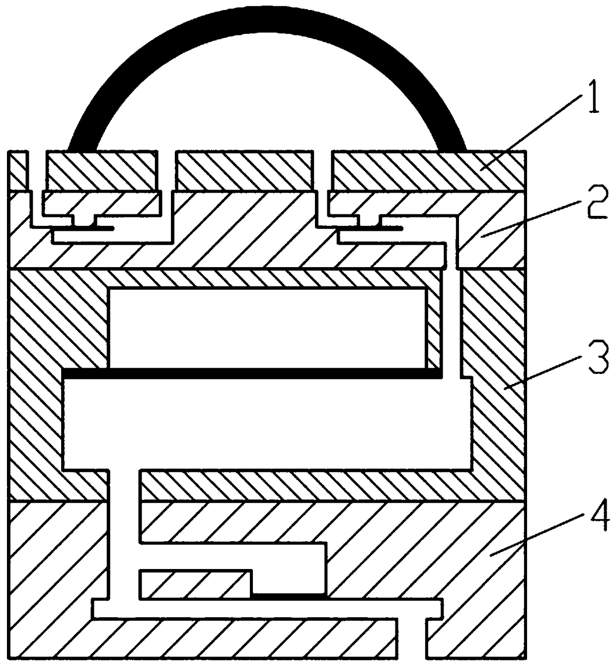
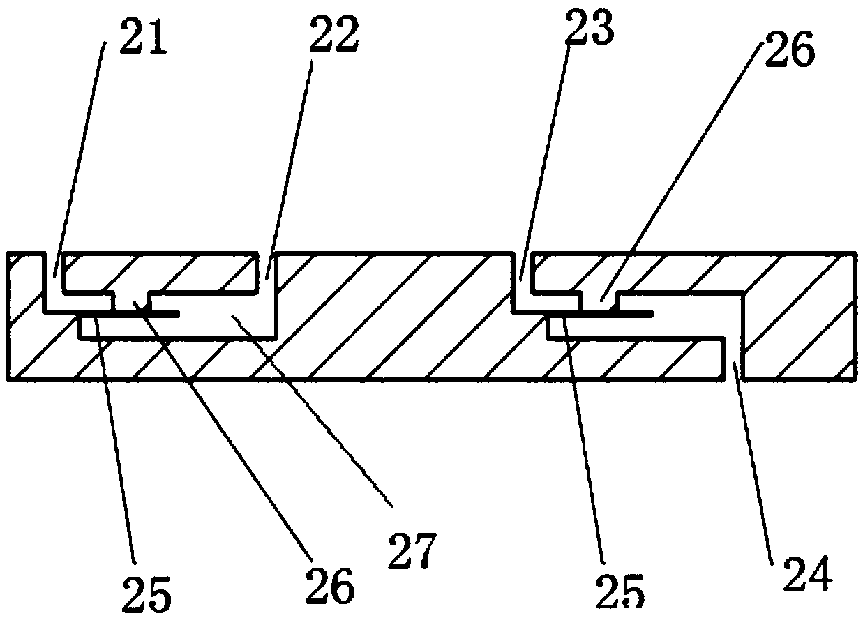
[0032] Such as Figure 1-5 As shown, the precision micropump driven by air pressure includes an air pressure module 1 , a one-way valve group 2 , a liquid storage module 3 and a flow regulation module 4 .

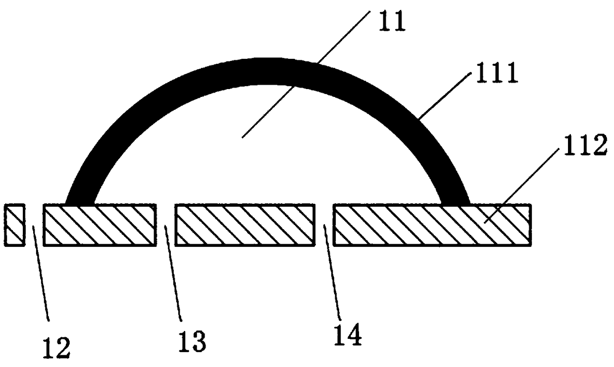
[0033] The air pressure module 1 is provided with an air bag 11, an outer hole 12, a first inner hole 13 and a second inner hole 14; the air bag 11 is surrounded by a bottom plate 112 and a curved wall 111, and the curved wall 111 is made of an elastic material, which can be restored to its original shape after extrusion. The bottom plate is connected with the one-way valve group 2. The bottom plate 111 is provided with an outer hole 12, a first inner hole 13 and a second inner hole 14. The outer hole 12 leads ...


PUM


Abstract

The invention relates to a pneumatic precision micropump, which comprises a pneumatic module, a check valve group, a liquid storage module and a flow regulation module. The pneumatic module comprisesan air bag; the check valve group comprises a first check valve and a second check valve, an inlet of the first check valve is communicated with the external atmosphere while an outlet is communicatedwith the air bag, and an inlet of the second check valve is communicated with the air bag while an outlet is communicated with the liquid storage module; the liquid storage module comprises a cavityand a liquid storage pool, the cavity and the liquid storage pool are spaced through a first elastic diaphragm, the cavity is a closed cavity, and the liquid storage pool is connected with the air bagthrough the second check valve; the flow regulation module comprises a first flow passage and a second flow passage, the first flow passage and the second flow passage are both communicated with theliquid storage pool, an outlet of the first flow passage is closed, an outlet of the second flow passage is communicated with the outside of the flow regulation module, and the first flow passage andthe second flow passage are spaced through a second elastic diaphragm. The pneumatic precision micropump has advantages of low starting pressure, stability in fluid delivery, small size, easiness in integration and the like, and microfluid stable driving and control demands are met.

Description

technical field [0001] The invention relates to the field of microfluidic chips, in particular to a precision micropump driven by air pressure. Background technique [0002] The continuous, stable and precise injection of sample liquid is an essential key link in the microfluidic system, and the accuracy and stability of microfluidic transport directly affect the functional performance of the microfluidic chip. At present, commercial instruments (such as precision syringe pumps, precision air pumps, etc.) are still the most frequently used microfluidic control means in microfluidic experiments and applications. Utilizing sophisticated sensing devices and mechanical and electronic controls, such instruments can achieve very precise microfluidic actuation and control. However, considering the high price and bulky volume, such instruments are not suitable for integrating low-cost, portable microfluidic systems. [0003] In order to achieve low-cost and precise microfluidic co...

Claims


Application Information

Patent Timeline
Patent Type & Authority Applications(China)
IPC IPC(8): B01L3/00
CPCB01L3/50273B01L2400/0487
Inventor 张鑫杰
Owner HOHAI UNIV CHANGZHOU
Learn More