
Pipe cutting machine

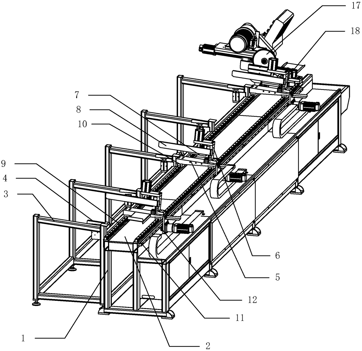
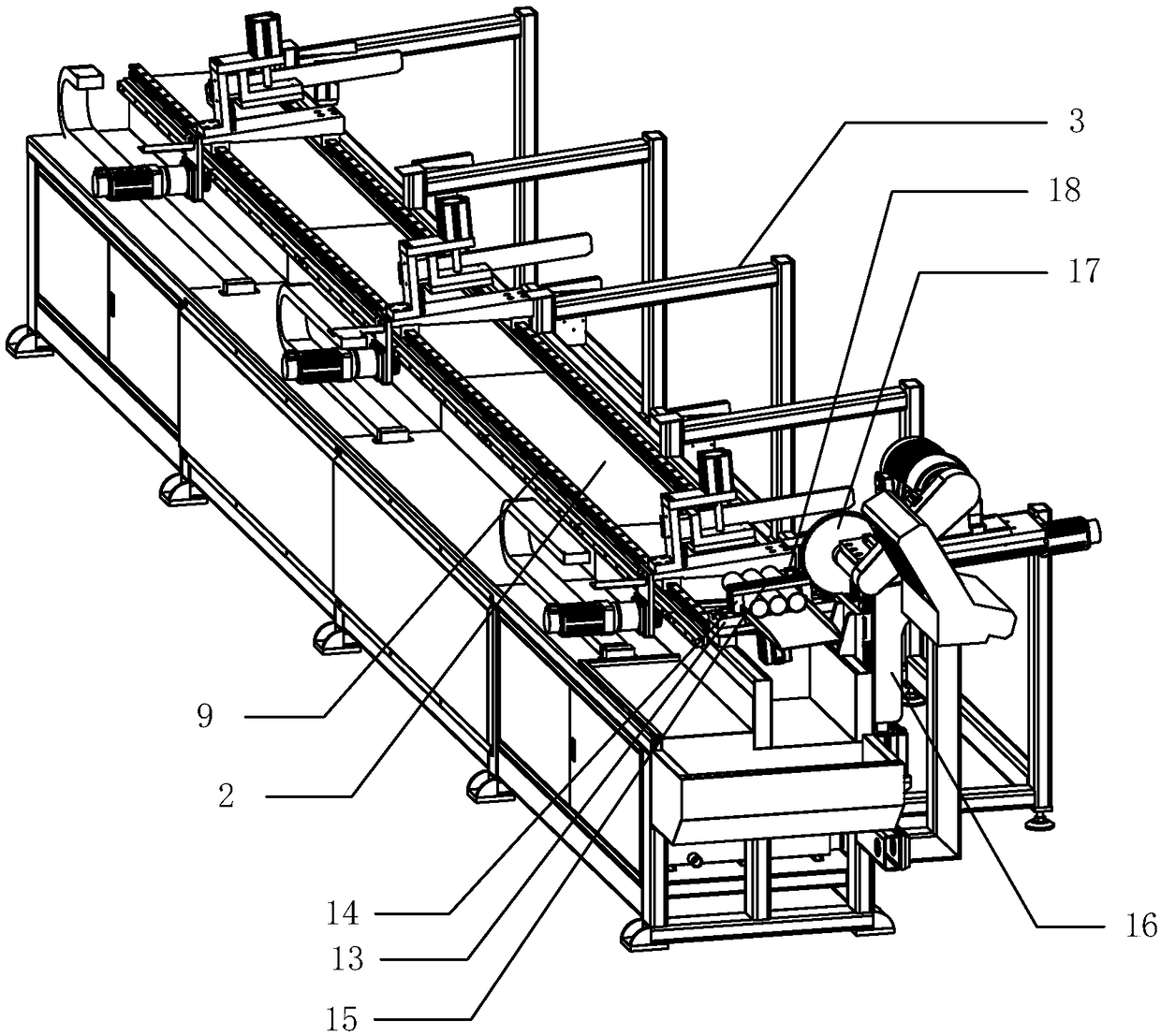
A technology of pipe cutting machine and cutting mechanism, applied in metal sawing equipment, sawing machine device, metal processing and other directions, can solve the problems of low pipe cutting positioning processing accuracy, large footprint, low processing efficiency, etc., and achieve overall structural equipment. Simple, improved processing efficiency, and the effect of improving processing efficiency

Pending Publication Date: 2019-02-19
佛山市顺德区凯铭威机械有限公司
View PDF0 Cites 0 Cited by
  • Summary
  • Abstract
  • Description
  • Claims
  • Application Information

AI Technical Summary

Problems solved by technology

[0002] The traditional pipe cutting machine occupies a large area and is complex. There are feeding devices and cutting devices along the length of the pipe. The feeding device stores the pipes to be cut, and continuously pushes the pipes to the cutting device to cut the pipes in sections. Such a structural design makes the volume of the equipment very large, which is difficult to adapt to modern processing and production. Some small pipe cutting machines reduce the feeding device, and only keep a small cutting device, which is continuously pushed into the cutting device manually. The tube method is more labor-intensive, and the tube cutting positioning processing accuracy is low, and the processing efficiency is low

Method used


Image

  • Pipe cutting machine
  • Pipe cutting machine

Examples


Embodiment Construction

[0020] The concept, specific structure and technical effects of the present application will be clearly and completely described below in conjunction with the embodiments and drawings, so as to fully understand the purpose, features and effects of the present application. Apparently, the described embodiments are only some of the embodiments of the present application, not all of them. Based on the embodiments of the present application, other embodiments obtained by those skilled in the art without creative efforts belong to The protection scope of this application. In addition, all connection relationships mentioned in this article do not refer to the direct connection of components, but mean that a better connection structure can be formed by adding or reducing connection accessories according to specific implementation conditions. The various technical features in the invention can be combined interactively on the premise of not conflicting with each other.

[0021] refer...


PUM


Abstract

The invention discloses a pipe cutting machine. The pipe cutting machine comprises a machine frame extending in the left-right direction; the top side of the machine frame is provided with a conveyingplatform extending left and right; the conveying platform is provided with one or more feeding mechanisms; the feeding mechanisms are provided with clamping inlets; the feeding mechanisms move back and forth in the length direction of the conveying platform; the clamping inlets of the feeding mechanisms face the front side or the rear side of the machine frame; one end of the conveying platform is provided with a pressing mechanism; and a cutting mechanism is provided beside the pressing mechanism. The overall structural design is simpler, the length of a machine body is shortened, the pipe cutting machine is more convenient to use, and the processing efficiency and quality are further improved.

Description

technical field [0001] The present application relates to a mechanical processing equipment, in particular to a pipe cutting machine. Background technique [0002] The traditional pipe cutting machine occupies a large area and is complex in equipment. A feeding device and a cutting device are installed along the length of the pipe. The feeding device stores the pipe to be cut and continuously pushes the pipe to the cutting device to cut the pipe in sections. Such a structural design makes the volume of the equipment very large, which is difficult to adapt to modern processing and production. Some small pipe cutting machines reduce the feeding device, and only keep a small cutting device, which is continuously pushed into the cutting device manually. The tube method is more manpower-intensive, and the positioning accuracy of the tube cutting is low, and the processing efficiency is low. Contents of the invention [0003] The technical problem to be solved in this applicati...

Claims


Application Information

Patent Timeline
IPC IPC(8): B23D47/04B23D45/12B23Q7/00
CPCB23D45/12B23D47/04B23D47/042B23Q7/00
Inventor 罗志城罗志辉
Owner 佛山市顺德区凯铭威机械有限公司
Learn More