Simple plastic packaging bag vacuumizing device

A vacuum device and packaging bag technology, applied in packaging, transportation and packaging, special packaging items, etc., can solve problems such as low work efficiency, unsuitable for batch production, unsatisfactory effects of pumping and preventing air from entering, and achieve Easy to operate, labor-saving, simple design, easy to take effect

Inactive Publication Date: 2019-02-19
岳西县祥瑞塑业有限公司
View PDF6 Cites 2 Cited by
  • Summary
  • Abstract
  • Description
  • Claims
  • Application Information

AI Technical Summary

Problems solved by technology

[0003] A prior art vacuum device for a plastic packaging bag (patent publication number CN202508413U) has a plastic packaging bag with a through hole in the middle of one plastic side, a valve base is arranged on the middle through hole of the plastic single side, and the other end of the valve base is set There is an upper cover matched with it, and a spring is arranged inside the upper cover, and the front end of the spring is a rubber valve arranged in the valve base to cooperate with it. Because the air in the plastic packaging bag is drawn out in the work of the present invention, the spring and the outside of the bag Under the action of air pressure, the rubber valve tightly presses the bottom plane in the round groove of the valve base, preventing the air outside the bag from re-entering; the device is not only compact in structure, but also convenient and practical, and can keep the plastic packaging bag in a vacuum for a long time. effect; but there are some drawbacks, each time can only extract the air of a group of packaging bags, not suitable for batch operation, low work efficiency, and for some larger packaging bags, the effect of pumping air and preventing air from entering is not good ideal, for this purpose, we propose a simple vacuum device for plastic packaging bags

Method used


Image

  • Simple plastic packaging bag vacuumizing device
  • Simple plastic packaging bag vacuumizing device
  • Simple plastic packaging bag vacuumizing device

Examples


Embodiment Construction

[0019] In order to make the technical means, creative features, goals and effects achieved by the present invention easy to understand, the present invention will be further described below in conjunction with specific embodiments.

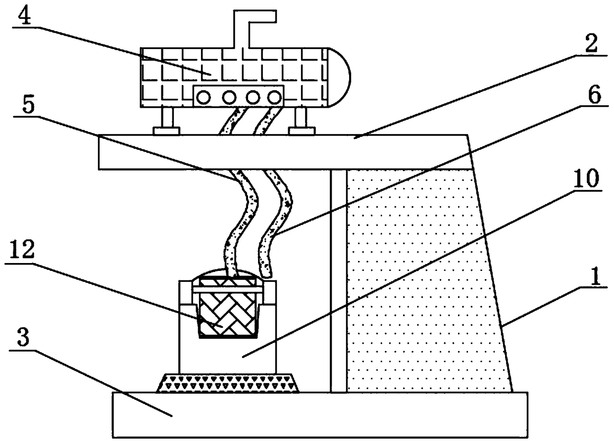
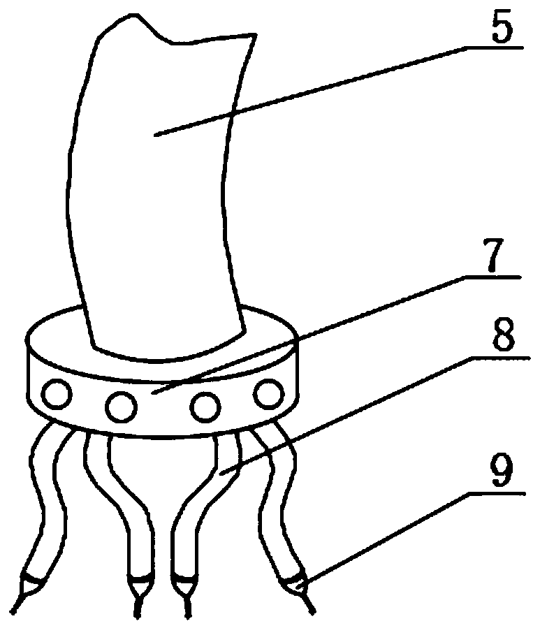
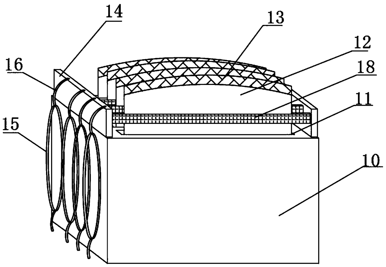
[0020] Such as Figure 1-4 As shown, a simple plastic packaging bag vacuuming device includes a device main body 1, the device main body 1 includes an upper support platform 2 and a lower support platform 3, the upper support platform 2 is located directly above the lower support platform 3, and the upper support platform 2 The upper end is provided with a vacuum pump 4, and the vacuum pump 4 passes downward through the interior of the upper support platform 2 and is connected with a suction hose 5 and a spare hose 6. The lower end of the suction hose 5 is threaded with a four-hole joint 7, and the four-hole Four sets of needle tubes 8 are symmetrically connected to the lower end surface of the joint 7, and four sets of connecting holes are opened...


PUM


Abstract

The invention discloses a simple plastic packaging bag vacuumizing device. The simple plastic packaging bag vacuumizing device comprises a device main body; the device main body comprises an upper supporting table and a lower supporting table; the upper supporting table is located over the lower supporting table; the upper end of the upper supporting table is provided with a vacuumizing pump, andthe vacuumizing pump penetrates through the upper supporting table downwards; the interior of the upper supporting table is connected with an air suction hose and a standby hose; and the lower end ofthe air suction hose is in threaded connection with a four-hole connector. The simple plastic packaging bag vacuumizing device is provided with the standby hose, sealing rings, concave-convex assemblies, an assembling seat and installing grooves, the hose damage problem is solved; packaging bags can be placed and conveniently spread and unfolded, the four packaging bags can be operated at a time,and the working efficiency is improved; and the four sealing rings are arranged orderly, are convenient to take and are used together, the sealing rings cooperate with the concave-convex assemblies toseal gaps formed by needles, and the situation that air enters the bags again during vacuumizing; and the simple plastic packaging bag vacuumizing device is suitable for different working conditions,and the better application prospects are brought.

Description

technical field [0001] The invention relates to the field of (dryer equipment), in particular to a simple vacuum pumping device for plastic packaging bags. Background technique [0002] Plastic packaging bag is a kind of packaging bag that uses plastic as raw material to produce various supplies in daily life. The commonly used plastic packaging bags are mostly made of polyethylene film. The film is non-toxic, so it can be used to hold food. There is also a The film is made of polyvinyl chloride, and polyvinyl chloride itself is non-toxic, but the additives added according to the use of the film are often harmful substances to the human body and have certain toxicity. [0003] A prior art vacuum device for a plastic packaging bag (patent publication number CN202508413U) has a plastic packaging bag with a through hole in the middle of one plastic side, a valve base is arranged on the middle through hole of the plastic single side, and the other end of the valve base is set T...

Claims


Application Information

Patent Timeline
Patent Type & Authority Applications(China)
IPC IPC(8): B65D81/20
CPCB65D81/2038
Inventor 王中岳
Owner 岳西县祥瑞塑业有限公司
Why Eureka
Try Eureka