

Side plate of foil generating machine and foil generating machine
A technology of raw foil machine and side plate, applied in electrolysis process, electroforming and other directions, can solve the problem of low temperature of solution in raw foil machine, and achieve the effect of reducing density, reducing parts and reducing influence
- Summary
- Abstract
- Description
- Claims
- Application Information
AI Technical Summary
Problems solved by technology
Method used
Image

Examples
Embodiment 1
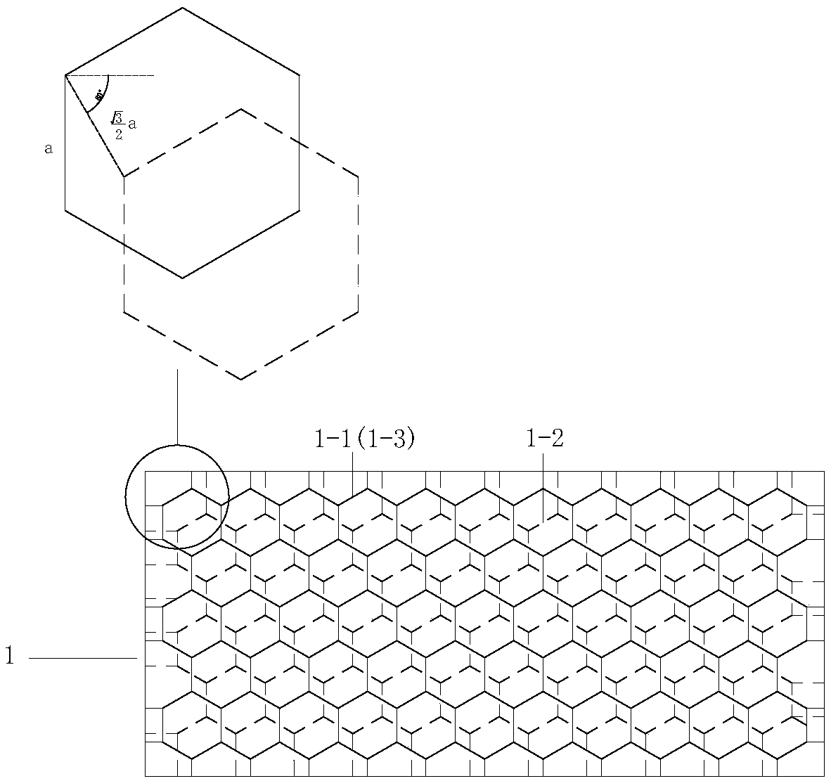
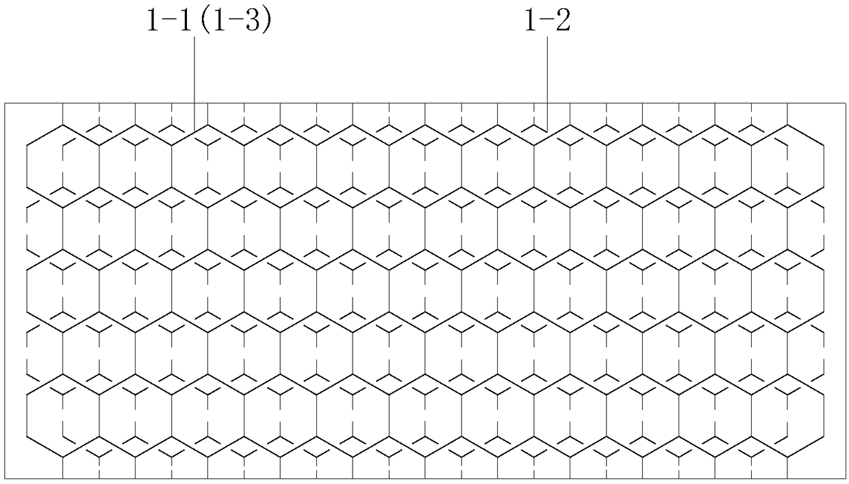
[0053] Embodiment 1, a foil machine side panel (1), the foil machine side panel (1) includes: a first frame (1-1), a second frame (1-2), a third frame (1-3 );
[0054] The first frame (1-1), the second frame (1-2), and the third frame (1-3) all include: the outer rectangular frame and the inner regular hexagonal unit structure, and the regular hexagonal unit structure The thickness is the same as that of the frame; the number of regular hexagonal unit structures is multiple;
[0055] The first frame (1-1) and the third frame (1-3) are arranged symmetrically on both sides of the second frame (1-2);
[0056] The regular hexagonal unit structure of the first frame (1-1) and the regular hexagonal unit structure of the second frame (1-2) are mutually staggered.
[0057] The regular hexagonal unit structures of the first frame (1-1), the second frame (1-2), and the third frame (1-3) have the same shape and size, and are all set in multiple rows and multiple columns;
[0058] Cove...
Embodiment 2
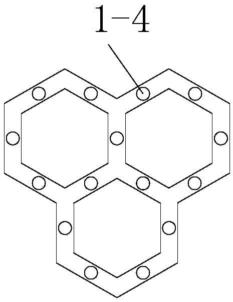
[0065] Embodiment two, such as Figure 3-4 As shown, there is a groove at the intersection of the regular hexagonal unit structure of the second frame (1-2), and a protruding threaded pipe (1-4) is set in the groove, and the threaded pipe (1-4) is a hollow pipe , and the outer surface is provided with threads;
[0066] The intersections of the regular hexagonal unit structures of the first frame (1-1) and the third frame (1-3) are also provided with grooves, and there are grooves corresponding to the threaded pipes (1-4) in the grooves. the insertion tube (1-5);
[0067] The shape of the insertion tube includes: the first section of the insertion tube and the second section of the insertion tube, the diameter of the first section of the insertion tube is larger than that of the second section of the insertion tube, and the second section of the insertion tube extends into the threaded pipe (1-4) , the outer side of the first section of the insertion tube is provided with thr...
Embodiment 3
[0072] Embodiment 3: In order to further improve the performance of the side plate, when the side plate of the foil machine in Embodiments 1 and 2 is applied to the foil machine, the third frame (1-3) faces the inside of the anode tank, in order to further adjust the anode tank The temperature of the inner solution, the regular hexagonal unit structure in the third frame adopts a square hollow tube structure, and the liquid is passed inside, and the liquid is adjusted to take away or transfer heat to the solution of the anode tank.
[0073] The regular hexagonal unit structure of the third frame has two vertical sides to ensure that the solution can flow away from top to bottom;
[0074] The regular hexagonal unit structures of the third frame are arranged at intervals in the rectangular frame (1-3-1) of the third frame, and each regular hexagonal unit structure (1-3-2) of the uppermost row of the third frame ) is connected to a vertical upper connecting frame (1-3-3), and an ...
PUM
 Abstract
Description
Claims
Application Information