Telescopic device of highway bridge

A telescopic device, highway bridge technology, applied in bridges, bridge parts, bridge construction and other directions, can solve the problems of accelerating the aging degree of rubber belts, easy to stick rubber belts, inconvenient to replace rubber belts, etc., to avoid sticking and replacement. The effect of the rubber belt is convenient and easy to operate

Inactive Publication Date: 2019-02-19
CHONGQING VOCATIONAL INST OF ENG
View PDF14 Cites 1 Cited by
  • Summary
  • Abstract
  • Description
  • Claims
  • Application Information

AI Technical Summary

Problems solved by technology

The telescopic device has the following problems: 1. The rubber belt of the device is exposed to the outside world, and is subjected to rolling by vehicles and soaking in rainwater, which accel

Method used


Image

  • Telescopic device of highway bridge
  • Telescopic device of highway bridge

Examples


Embodiment Construction

[0016] The following is further described in detail through specific implementation methods:

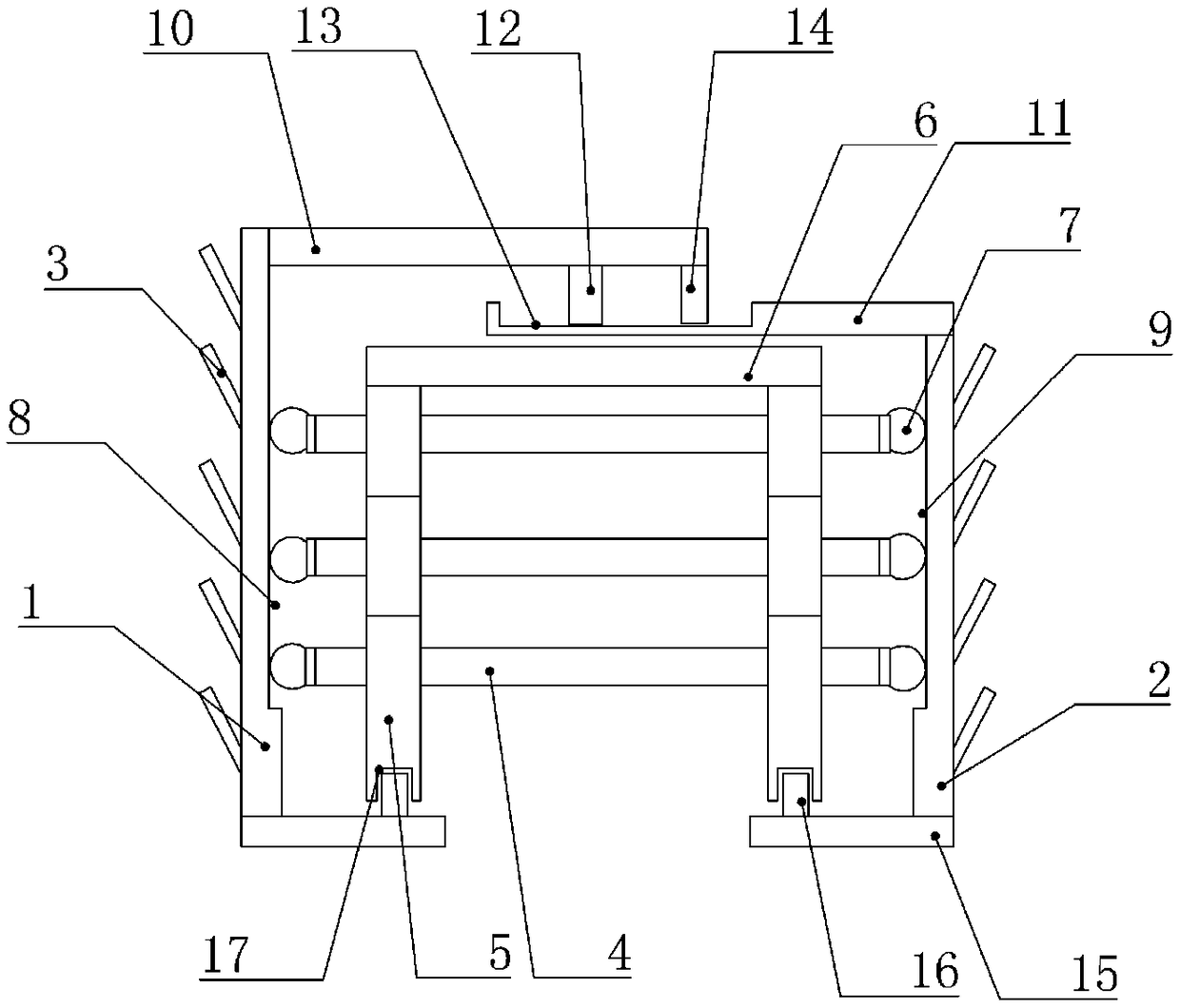
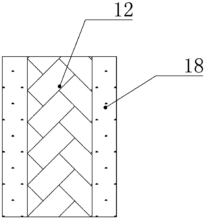
[0017] The reference signs in the accompanying drawings of the description include: first fixed plate 1, second fixed plate 2, metal sheet 3, rubber belt 4, vertical rod 5, elastic strip 6, roller 7, first chute 8, second The chute 9 , the first extension plate 10 , the second extension plate 11 , the slider 12 , the third chute 13 , the sealing block 14 , the support plate 15 , the first bump 16 , the first groove 17 , and the deformation layer 18 .

[0018] Example figure 1 and figure 2 Shown: a telescopic device for a highway bridge, including a telescopic mechanism, a first fixed plate 1 and a second fixed plate 2, the first fixed plate 1 and the second fixed plate 2 are vertically arranged, and the telescopic mechanism is located on the first fixed plate Between 1 and the second fixed plate 2, the first fixed plate 1 and the second fixed plate 2 are made of steel, and the out...


PUM


Abstract

The invention relates to the technical field of highway bridges, and discloses a telescopic device of a highway bridge. The telescopic device comprises a telescopic mechanism and two vertically arranged fixed plates. The telescopic mechanism is located between the two fixed plates, a plurality of metal sheets are arranged on the outer sides of the fixed plates at equal intervals, and the metal sheets are arranged upwards obliquely. The telescopic mechanism comprises a plurality of rubber belts and a plurality of vertical rods, the rubber belts are perpendicular to the fixed plates, the rubberbelts are arranged in parallel and connected through the vertical rods, extending plates are hinged to the upper ends of the two fixed plates, the extending plates are overlapped and are in sliding connection, the lower ends of the two fixed plates are horizontally connected with supporting plates, and a clearance is arranged between the two supporting plates. The vertical rods are divided into aplurality of branch rods, and the branch rods are detachably connected. According to the telescopic device, the rubber belts are protected, and the rubber belts can be replaced conveniently.

Description

technical field [0001] The invention relates to the technical field of highway bridges, in particular to a telescopic device for highway bridges. Background technique [0002] With the rapid development of my country's economic construction, high-grade highways represented by expressways have sprung up, and the traffic volume of highways has increased sharply. The speed of vehicles driving on the highways and the axle load of vehicles are increasing. The requirements are getting higher and higher, so in the past bridge design and construction, problems related to expansion devices that were not paid enough attention have become more and more prominent, forcing bridge design, construction, maintenance and management departments to pay full attention to this. The road bridge expansion device is mainly installed at the expansion joint between the two parts of the bridge beam body. It directly bears the repeated impact of the wheel load in the bridge structure, and is exposed to ...

Claims


Application Information

Patent Timeline
IPC IPC(8): E01D19/06
CPCE01D19/06
Inventor 李书芳
Owner CHONGQING VOCATIONAL INST OF ENG
Why Eureka
Try Eureka