
Foundation pit soldier pile supporting system and construction method thereof

A technology for foundation pit and earthwork, which is applied in basic structure engineering, excavation, construction, etc., can solve the problems of inability to meet the needs of foundation pit support, difficult construction, affecting construction period, etc., to achieve good promotion and practical value, and save construction period. , The effect of supporting high safety

Pending Publication Date: 2019-02-19
CHINA CONSTR FIRST BUILDING GRP CORP LTD
View PDF0 Cites 3 Cited by
  • Summary
  • Abstract
  • Description
  • Claims
  • Application Information

AI Technical Summary

Problems solved by technology

[0003] The purpose of the present invention is to provide a foundation pit row pile support system and its construction method, to solve the technical problem that the single support method in the prior art has no way to meet the needs of foundation pit support; and to solve the serious problem of traditional horizontal support forms. Problems that affect the construction period and are difficult to construct

Method used


Image

  • Foundation pit soldier pile supporting system and construction method thereof
  • Foundation pit soldier pile supporting system and construction method thereof
  • Foundation pit soldier pile supporting system and construction method thereof

Examples


Embodiment Construction

[0030] In order to make the technical means, innovative features, goals and effects achieved by the present invention easy to understand, the present invention will be further described below.

[0031] The examples described here are specific specific implementations of the present invention, and are used to illustrate the concept of the present invention. They are all explanatory and exemplary, and should not be construed as limiting the implementation of the present invention and the scope of the present invention. In addition to the embodiments described here, those skilled in the art can also adopt other obvious technical solutions based on the claims of the application and the contents disclosed in the description, and these technical solutions include adopting any obvious changes made to the embodiments described here. Replacement and modified technical solutions.

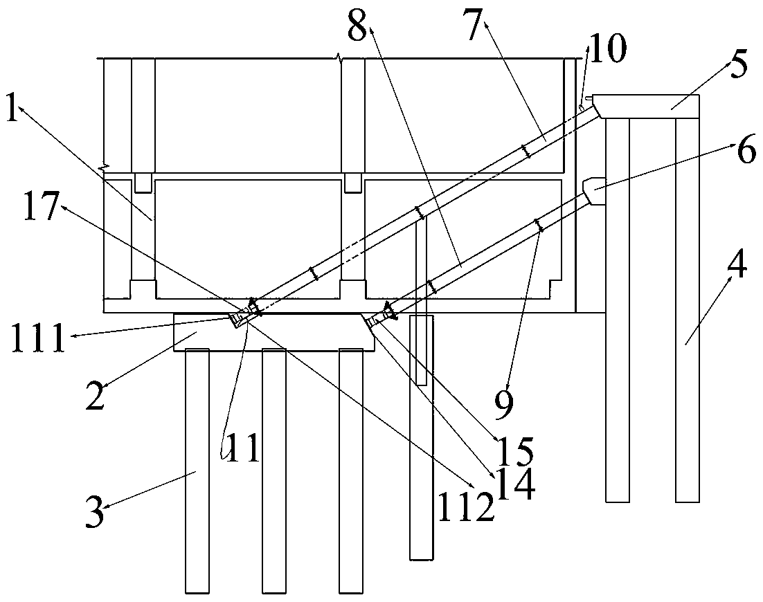
[0032] A pile row support system for a foundation pit, comprising a diagonally braced pile foundation cap,...


PUM


Abstract

The invention relates to a foundation pit soldier pile supporting system and a construction method thereof. The foundation pit soldier pile supporting system comprises a diagonal brace pile foundationcushion cap, a soldier pile structure and a plurality of groups of diagonal braces supported between the diagonal brace pile foundation cushion cap and the soldier pile structure; the diagonal bracepile foundation cushion cap comprises a supporting platform and supporting piles; the supporting platform is positioned under a structure wall body; the supporting piles are supported at the bottom ofthe supporting platform; the soldier pile structure comprises a soldier pile, a crown beam and a breast beam; the crown beam is arranged on the top surface of the soldier pile; the breast beam is arranged in the middle of the soldier pile and faces one side of a foundation pit; and each group of the diagonal braces comprises a steel diagonal brace I arranged between the crown beam and the supporting platform. Under the conditions that an underground structure is heavy in construction task, the construction period is tight, and the surrounding environment is complicated, the supporting safetyrequired in design is very high, the supporting requirements of most of foundation pits can be met by applying steel diagonal braces with the pile caps as foundations onto the crown beam and the breast beam of the soldier pile, and in addition, diagonal bracing replaces horizontal bracing, so that the problem that the construction of the foundation pit is affected by cumbersome processes such as horizontal bracing removing is solved, and the construction period is saved.

Description

technical field [0001] The invention belongs to the field of foundation pit support, in particular to a foundation pit row pile support system and a construction method thereof. Background technique [0002] With the growth of the city, it has become inevitable to develop large-scale underground space in combination with urban construction and renovation. These deep and large foundation pits are often close to buildings, traffic arteries, subway tunnels and various underground pipelines. The construction site is tight and the construction conditions are complex. Due to the tight construction period, all these make the design and construction of foundation pit engineering more and more difficult. At present, the main forms of foundation pit support include natural slope, soil nail wall, single (double) row of piles, underground diaphragm wall, etc., but due to Due to the complexity around the foundation pit, the traditional or single support form can no longer fully meet the ...

Claims


Application Information

Patent Timeline
IPC IPC(8): E02D17/04E02D27/14
CPCE02D17/04E02D27/14
Inventor 金晓飞刘洪刚庄小杰吕善勇崔婧瑞焦景毅杨旭东滕孝鑫朱友龙庞戈
Owner CHINA CONSTR FIRST BUILDING GRP CORP LTD
Learn More