Track deformation control structure arranged in shield tunnel with bottom corridor

A shield tunneling and deformation control technology, applied in the directions of tracks, tunnels, roads, etc., can solve the problems of limited length of deformation rings, inability to fully meet the safety and stability of shield tunnels, and reduced shock absorption effect. Simple deformation mode, ensure operational safety, and reduce the effect of derailment accidents

Pending Publication Date: 2019-02-19
CHINA RAILWAY SIYUAN SURVEY & DESIGN GRP
View PDF17 Cites 5 Cited by
  • Summary
  • Abstract
  • Description
  • Claims
  • Application Information

AI Technical Summary

Problems solved by technology

This method is suitable for the case where the span of the junction between soft and hard formations is small, otherwise the shock absorption effect will be greatly reduced due to the limited length of the deformation ring
[0004] In addition, when the flexible joint structure is used in shield tunnels, for shield tunnels with bottom corridors, since the track slabs and shield tunnel segments are constrained by prefabricated box culverts, cast-in-place corbels and cast-in-place driveway slabs, etc. Therefore, when the earthquake acts, the displacement of the tunnel structure will cause dislocation along with the track, or the track will be seriously twisted. When the train passes through this section, it may cause the train to derail, and in severe cases, it will cause the train to overturn. Hit the tunnel wall, causing damage to the tunnel structure, which in turn leads to more serious secondary disasters
Therefore, the existing track structure installed in the shield tunnel with the bottom corridor cannot fully meet the safety and stability of the shield tunnel during the use of the earthquake, and there are certain limitations

Method used


Image

  • Track deformation control structure arranged in shield tunnel with bottom corridor
  • Track deformation control structure arranged in shield tunnel with bottom corridor

Examples


Embodiment Construction

[0028] In order to make the object, technical solution and advantages of the present invention clearer, the present invention will be further described in detail below in conjunction with the accompanying drawings and embodiments. It should be understood that the specific embodiments described here are only used to explain the present invention, not to limit the present invention.

[0029] In addition, the technical features involved in the various embodiments of the present invention described below can be combined with each other as long as they do not constitute a conflict with each other.

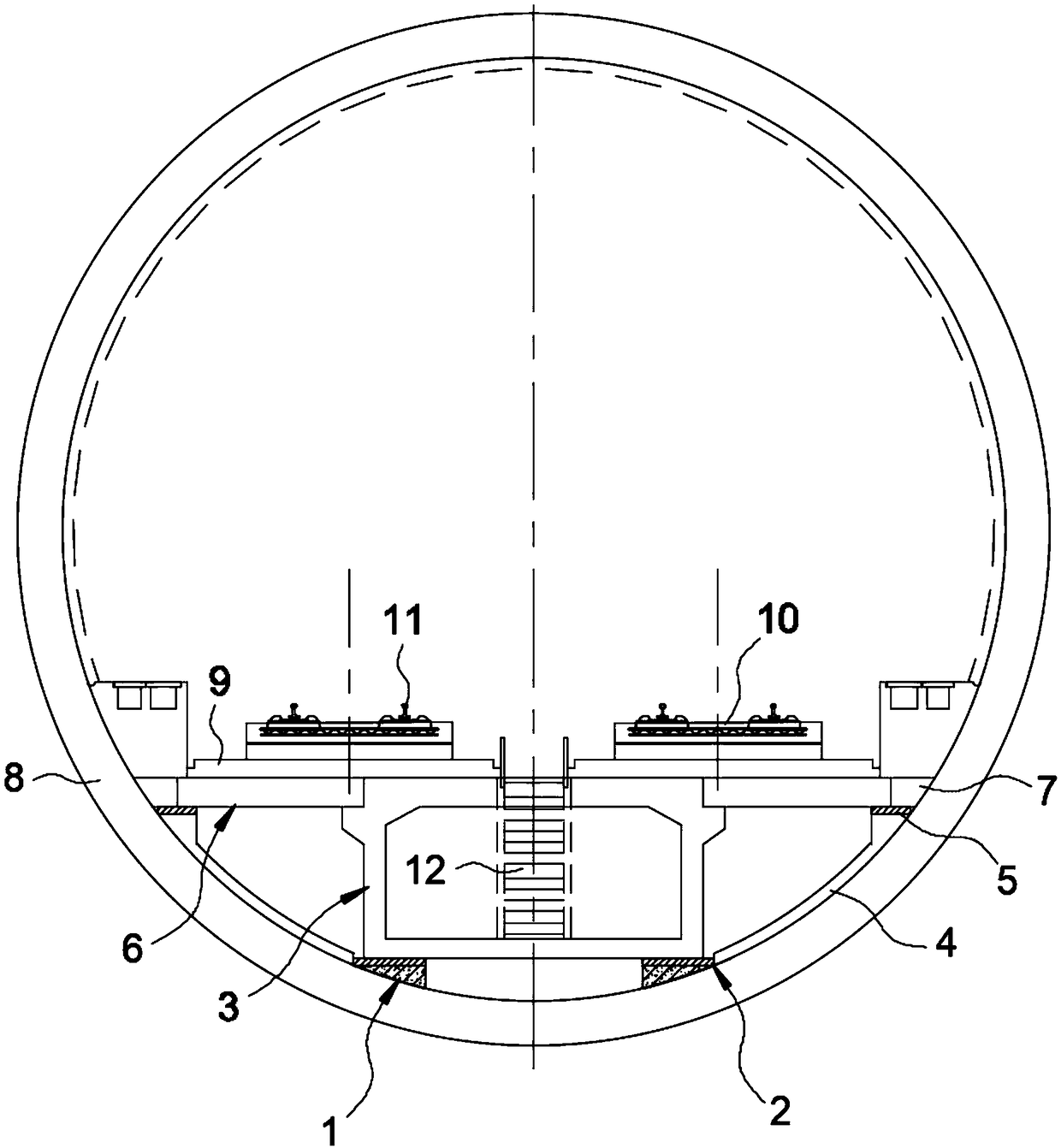
[0030] In the preferred embodiment of the present invention, the track deformation control structure arranged in the shield tunnel with the bottom corridor is as follows: figure 1 As shown in , wherein, the shield tunnel is a continuous "tubular" structure formed by splicing a number of shield segments 8 correspondingly along the longitudinal direction, and the shield tunnel includes the ...


PUM


Abstract

The invention discloses a track deformation control structure arranged in a shield tunnel with a bottom corridor, and belongs to the correlation technical field of shield tunnel. According to the raildeformation control structure arranged in the shield tunnel with the bottom corridor, a middle box culvert can drive a field cast road face plate, a carriageway plate, a track plate and other mechanisms in the event of earthquake to not completely lateral swinging with a tunnel structure due to the fact that the middle box culvert with a rectangular section is longitudinally arranged at the bottom of the shield tunnel, a supporting platform, an arc-shaped plate, a partition plate and a sliding cushion layer are arranged correspondingly, and the large radius curve deformation of the track is realized and the normal operation of a train in the shield tunnel is achieved when the earthquake occurs. The track deformation control structure has simple structure and low setting costs, the normaloperation of the track structure in the shield tunnel with the bottom corridor is ensured under earthquake action, the safety and stability of the shield tunnel operation are improved, the possible damage of a track structure and a tunnel structure during earthquake is reduced, the safe operation of the shield tunnel is ensured, and a great value for popularization and application is achieved.

Description

technical field [0001] The invention belongs to the related technical field of shield tunnels, and in particular relates to a track deformation control structure arranged in a shield tunnel with a bottom corridor. Background technique [0002] In tunnel construction technology, the shield tunneling method is a fully mechanized construction method for underground excavation of tunnels. It often has the advantages of safe construction, fast excavation speed, good engineering quality, strong adaptability to complex strata, small surface settlement, and good influence on the surrounding environment. With many advantages such as small impact, it has become one of the main construction methods of tunnel engineering, and has been widely used in urban subways, urban railways, municipal roads and infrastructure, and underwater tunnels. In the construction of shield tunnels, it is inevitable to pass through the weak and broken zone. Since the repair of the damaged underground structur...

Claims


Application Information

Patent Timeline
Patent Type & Authority Applications(China)
IPC IPC(8): E21D9/06E21F13/00E21F17/00E01B13/00E01B19/00
CPCE21D9/06E21F13/00E21F17/00E01B13/00E01B19/00
Inventor 肖明清王少锋邓朝辉周坤龚彦峰徐晨
Owner CHINA RAILWAY SIYUAN SURVEY & DESIGN GRP
Why Eureka
Try Eureka