High-precision heavy-load thick roller shaft system for speed reducer

A roller shaft, high-precision technology, applied in transmission parts, belts/chains/gears, mechanical equipment, etc., can solve problems such as insufficient torsion resistance, poor impact resistance, and short service life of the whole machine, achieving Increase the load and impact resistance, improve the axial and radial stiffness, and improve the effect of high torque resistance

Pending Publication Date: 2019-02-19
中核新科(天津)科技有限公司
View PDF15 Cites 0 Cited by
  • Summary
  • Abstract
  • Description
  • Claims
  • Application Information

AI Technical Summary

Problems solved by technology

At present, the load-bearing bearings of the output shaft of reducers commonly used at home and abroad are angular contact bearing pairs, and the supporting positions are on both sides of the output shaft. The output shaft needs to carry the entire weight of the lower-level mechanical arm and the clamped workpiece, and operates under heavy load conditions for a long time. Therefore, it is difficult for the internal support shaft system to maintain high-precision rotation for a long time, and the gears are severely worn, which leads to The high-precision life cycle of the reducer is seriously insufficient, and frequent repairs or replacements are required
Analysis of the reason is the problem of the bearing support method. At present, the shaft system of the mainstream reducer in the industry is generally only used to achieve torque output. When the shaft system inside the reducer needs to undertake the functions of precision rotation and heavy load support at the same time, especially when the reducer When the internal space is limited and only one set of angular contact bearings can be installed, in this case, the rotation accuracy of the output shaft of the reducer under heavy load conditions cannot be guaranteed
The reducer for industrial robots needs to meet the multi-degree-of-freedom rotation under heavy load conditions. Therefore, when the radial and axial loads and torsion resistance of the bearing are required to be high, the load capacity of the conventional bearing cantilever support method is insufficient. , especially the twist resistance is obviously insufficient, the impact resistance is poor, and the service life of the whole machine is short

Method used


Image

  • High-precision heavy-load thick roller shaft system for speed reducer
  • High-precision heavy-load thick roller shaft system for speed reducer
  • High-precision heavy-load thick roller shaft system for speed reducer

Examples


Embodiment Construction

[0034] The following is a detailed description of the high-precision heavy-duty dense roller shafting for the reducer of the present invention in conjunction with the drawings and embodiments of the specification:

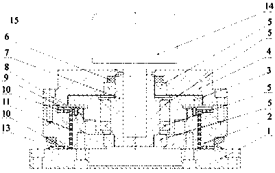
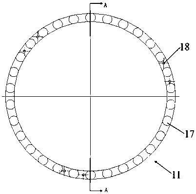
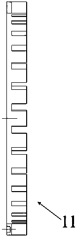
[0035] Such as Figure 1~5 As shown, a high-precision heavy-duty dense roller shaft system for a reducer includes a motor 14, and its motor shaft 15 is assembled in a deep hole in the center of the input shaft 7, and the input shaft 7 is equipped with a stepped wheel 3 outside, and both A bearing 5 is arranged between them; the step wheel 3 is externally assembled with an output shaft 8, and a bearing 5 is arranged between the output shaft 8 and the input shaft 7; the output shaft 8 is externally assembled with a body 2; the body 2 and the top of the step wheel 3 are assembled with an input end cover 4 Between the input end cover 4 and the input shaft 7, there are bearings 5 ​​and inner sleeves 6 in order from bottom to top; the input end cover 4 and the body 2 are...


PUM


Abstract

The invention discloses a high-precision heavy-load thick roller shaft system for a speed reducer. The high-precision heavy-load thick roller shaft system for the speed reducer comprises a motor; a motor shaft is assembled in a deep hole of an input shaft; a step wheel is assembled out of the input shaft, and a bearing is arranged between the two; an output shaft is assembled out of the step wheel; a bearing is arranged between the output shaft and the input shaft; a main body is assembled out of the output shaft; an input end cover is assembled above the main body and the step wheel; a bearing and a sealing cover are arranged between the input end cover and the input shaft; the input end cover and the main body are fastened through screws; an output disc is arranged under the output shaftand the main body, and is connected with the bottom of the output shaft through screw fastening pieces; an outer oil seal sleeve is arranged in a clamping groove on the outer wall at the lower end ofthe main body; a radial thick roller shaft system is arranged between the output shaft and the main body; axial thick roller shaft systems are arranged on the upper and lower end surfaces of the mainbody; a cover disc is assembled above the axial thick roller shaft system on the upper end; and the cover disc is fixed on the top surface of the output shaft. The high-precision heavy-load thick roller shaft system for the speed reducer can improve the load and the impact resistance of the speed reducer to the greatest extent, and prolongs the anticipant life of the speed reducer.

Description

technical field [0001] The invention belongs to the technical field of motor reducers, and in particular relates to a high-precision heavy-duty dense roller shaft system for a reducer. Background technique [0002] The gear reducer is a commonly used transmission mechanism in the machinery industry. Its principle is to realize the variable speed of the motor output through multi-stage gear meshing transmission, and at the same time realize the variable torque output. At present, the load-bearing bearings of the output shaft of reducers commonly used at home and abroad are angular contact bearing pairs, and the supporting positions are on both sides of the output shaft. The output shaft needs to carry the entire weight of the lower-level mechanical arm and the clamped workpiece, and operates under heavy load conditions for a long time. Therefore, it is difficult for the internal support shaft system to maintain high-precision rotation for a long time, and the gears are severe...

Claims


Application Information

Patent Timeline
Patent Type & Authority Applications(China)
IPC IPC(8): F16H57/023F16H57/021F16H57/029
CPCF16H57/021F16H57/023F16H57/029
Inventor 齐铁城王斌吴艳青李正海陈景华杨力姚连波
Owner 中核新科(天津)科技有限公司
Why Eureka
Try Eureka