Electromagnetic valve device with backflow preventing function and automatic sewage isolating function

A technology of anti-backflow and solenoid valve, which is applied in the direction of valve device, function valve type, valve operation/release device, etc. It can solve the problems of water splashing, unreasonable structure, and large space occupied, so as to avoid the backflow of sewage , compact structure and easy assembly

Pending Publication Date: 2019-02-19
宁波展鹰智能卫浴科技有限公司
View PDF0 Cites 2 Cited by
  • Summary
  • Abstract
  • Description
  • Claims
  • Application Information

AI Technical Summary

Problems solved by technology

[0002] The solenoid valve flushing device currently used in the market, due to the limitation of the mold structure, the valve body is a split structure, with two valve bodies on the left and right, and a tee in the middle to connect the valve bodies on both sides, which occupies a relatively large space and requires installation and maintenance. Relatively cumbersome, the connection between the valve body and the valve body is prone to water leakage
The split valve body has three parts, which is costly and not economical and practical; in addition, the water inlet connection of the split valve body is generally threaded, and the assembly process is cumbersome and time-consuming.
[0003] When the existing sol...

Method used


Image

  • Electromagnetic valve device with backflow preventing function and automatic sewage isolating function
  • Electromagnetic valve device with backflow preventing function and automatic sewage isolating function
  • Electromagnetic valve device with backflow preventing function and automatic sewage isolating function

Examples


Embodiment Construction

[0026] The present invention will be further described in detail below in conjunction with the accompanying drawings and embodiments.

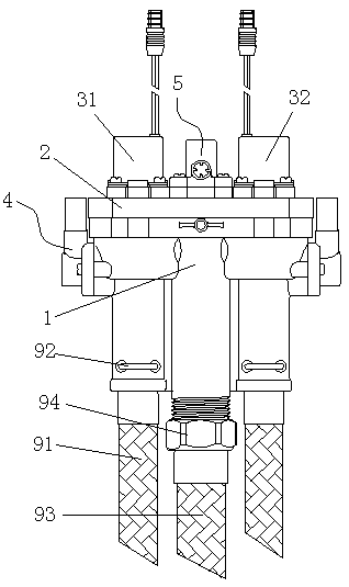
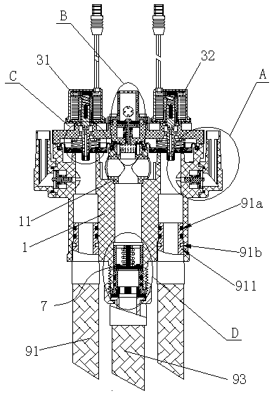
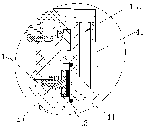
[0027] Such as Figure 1 to Figure 8 Shown is the structural representation of the present invention,

[0028] The reference signs are: valve body 1, water inlet 1a, first water outlet 1b, second water outlet 1c, vacuum breaking hole 1d, cleaning waterway interface 1e, four-way insert 11, filter screen 12, valve cover 2 , the first flushing solenoid valve 31, the second flushing solenoid valve 32, the vacuum breaking device 4, the vacuum breaking valve cover 41, the vent 41a, the vacuum breaking valve core 42, the vacuum breaking spring 43, the sealing rubber film 44, the anti-siphon device 5 , anti-siphon cover 51, air inlet 51a, overflow hole 51b, anti-siphon core 52, anti-siphon spring 53, anti-siphon rubber film 54, sealing diaphragm 61, diversion tube 62, pressure relief hole 62a, anti-blocking needle Spring 63, booster hole 64, one-way...


PUM


Abstract

The invention discloses an electromagnetic valve device with a backflow preventing function and an automatic sewage isolating function. The electromagnetic valve device with the backflow preventing function and the automatic sewage isolating function comprises a valve body and a valve deck which are matched with each other. The valve deck is provided with a first flushing electromagnetic valve anda second flushing electromagnetic valve. The valve body is of an integrated structure. A four-way embedded piece is assembled in the middle of the valve body. The valve body is provided with a waterinlet, a first water outlet and a second water outlet, wherein the water inlet, the first water outlet and the second water outlet communicate. The first water outlet and the second water outlet communicate with vacuum breakers on the corresponding sides correspondingly. Each vacuum breaker comprises a vacuum breaking valve deck, a vacuum breaking valve element, a vacuum breaking spring and a sealrubber film, wherein the vacuum breaking valve deck is provided with a vent opening, the vacuum breaking valve element is arranged in the vacuum breaking hole of the valve body, the vacuum breaking spring is arranged between the vacuum breaking valve element and the valve body, and the seal rubber film is arranged outside the vacuum breaking valve element. The valve deck is provided with an anti-siphon device. A seal membrane sheet is arranged at the valve opening between the valve body and the valve deck. The electromagnetic valve device with the backflow preventing function and the automatic sewage isolating function has the advantages of being compact in structure and convenient to assemble and maintain.

Description

technical field [0001] The invention relates to the technical field of electromagnetic valve manufacturing, in particular to an electromagnetic valve device with the functions of anti-reflux and automatic dirt isolation. Background technique [0002] The solenoid valve flushing device currently used in the market, due to the limitation of the mold structure, the valve body is a split structure, with two valve bodies on the left and right, and a tee in the middle to connect the valve bodies on both sides, which occupies a relatively large space and requires installation and maintenance. Comparing loaded down with trivial details, the joint between valve body and valve body is easy to leak. The split valve body has three parts, which is costly and not economical and practical; in addition, the water inlet connection of the split valve body is generally threaded, and the assembly process is cumbersome, time-consuming and laborious. [0003] When the existing solenoid valve flu...

Claims


Application Information

Patent Timeline
IPC IPC(8): F16K31/06F16K27/08F16K17/19F16K7/12
CPCF16K31/0641F16K7/12F16K17/19F16K27/08
Inventor 应俊
Owner 宁波展鹰智能卫浴科技有限公司
Why Eureka
Try Eureka