Concrete pump pipe supporting device and using method thereof

A technology for concrete pump pipes and support devices, which is applied in the direction of pipe supports, hoses, pipes, etc., which can solve the problems of poor deformation performance, poor deformation resistance, and poor deformation resistance of concrete pump pipes, and achieve improved buffering Shock absorption effect, good deformation resistance, and improved anti-slip performance

Pending Publication Date: 2019-02-19
SHANDONG SANJIAN CONSTR ENG +1
View PDF2 Cites 0 Cited by
  • Summary
  • Abstract
  • Description
  • Claims
  • Application Information

AI Technical Summary

Problems solved by technology

[0002] At present, in the construction process of construction projects, it is often necessary to pour concrete on the roof of garages and other projects. The prior art method is to use automobile tires as pads under the concrete pump pipe, that is, to place the automobile tires on the concrete pump pipe and the roof of the garage. Between the steel bars to buffer the impact force of the concrete pump pipe, but its effect is poor, because the impact force of the concrete pump pipe on the support structure of the garage roof formwork and its bracket is very large, resulting in the collapse of the support of the garage roof formwork risk issue
[0003] The Chinese invention patent document with the notification number CN108087491A discloses a shock-absorbing concrete pump pipe horizontal support device, which includes a base, a height adjustment part, a frame body, a shock-absorbing part, and a pump pipe fixing part. The part is installed on the base, and the pump pipe fixing part is arranged on the frame body through the shock absorbing part. Although it can fix and damp the concrete pump pipe, it has the effect on the concrete pump pipe. The deformation performance of the fixed part is poor, resulting in the problem of poor cushioning performance
[0004] The Chinese utility model patent document with the notification number CN206309039U discloses a movable pump tube support device that can be assembled, which includes a support plate, on which a pump tube is arranged, and the pump tube passes through several pumps arranged above the support plate. The tube fixing part is fixed on the support plate, and there are connecting mechanisms at the left and right ends of the pump tube; there are several telescopic outriggers under the support plate, and the top of the telescopic outriggers is connected with the support plate. Wheels are provided at the bottom of the bottom of the support plate; a telescopic support leg is respectively provided on the front and rear sides of the middle part of the bottom of the support plate, and a support is provided below the telescopic support leg; the bottom of the support has a large friction coefficient, although it can support the concrete pump pipe, it also has the problem of poor deformation resistance, resulting in poor cushioning performance
[0005] To sum up, the shock-absorbing support devices for concrete pump pipes in the prior art mostly adopt a single-dimensional shock-absorbing structure, which often has poor deformation resistance, resulting in poor cushioning performance.

Method used


Image

  • Concrete pump pipe supporting device and using method thereof
  • Concrete pump pipe supporting device and using method thereof

Examples


Embodiment 1

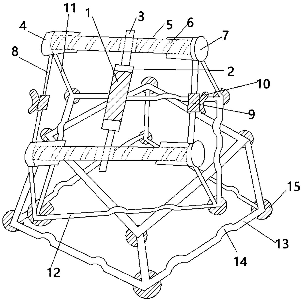
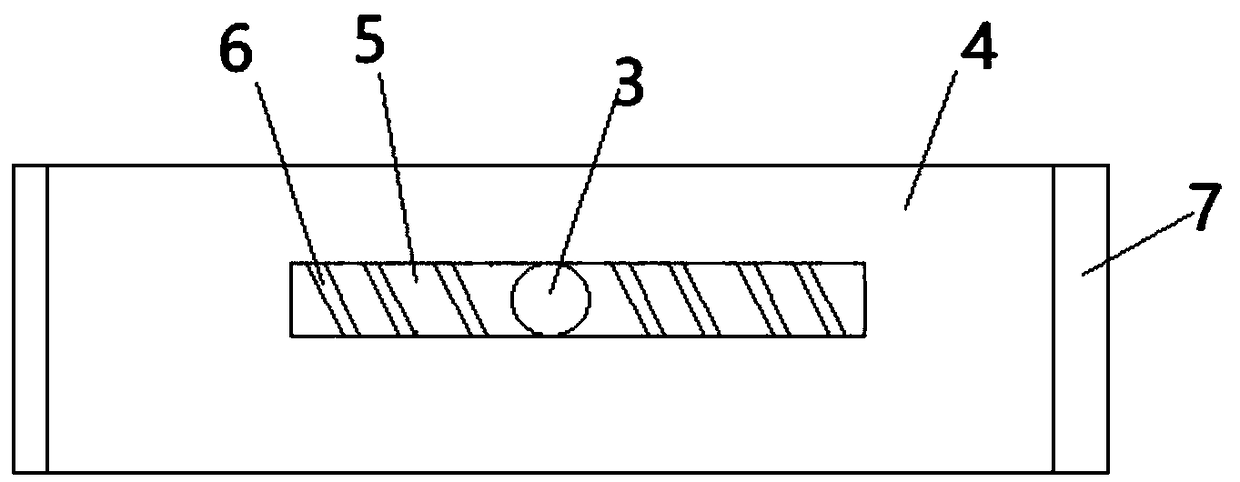
[0023] A concrete pump pipe support device, see figure 1 , the concrete pump pipe supporting device includes a circular tubular bearing tube 1, the bearing tube 1 is sleeved on a cylindrical supporting shaft 2, and both ends of the supporting shaft 2 are concentrically connected with the inner end of the cylindrical rotating shaft 3 , the outer diameter of the supporting shaft 2 is greater than the outer diameter of the rotating shaft 3; the outer end of the rotating shaft 3 is provided with a tubular buffer tube 4, the central axis of the buffer tube 4 is perpendicular to the central axis of the rotating shaft 3, see figure 2 The side walls of the buffer tube 4 are provided with through-hole openings 5, and the outer ends of the rotating shaft 3 respectively pass through the openings 5; the left and right sides of the rotating shaft 3 are respectively provided with buffer springs 6 located in the buffer tube 4, Both the left end and the right end of the buffer tube 4 are pro...

Embodiment 2

[0032] A concrete pump pipe support device is similar to Embodiment 1, the difference is that the outer end of the rotating shaft 3 is provided with a baffle. In this way, the rotating shaft 3 can be prevented from slipping out of the opening 5 due to its movement. The baffle can be a metal plate, and the baffle and the rotating shaft 3 can be connected by welding or screws. The baffle can be a circular plate or a rectangular plate. The outer diameter of the baffle should be larger than the outer diameter of the opening 5 .

Embodiment 3

[0034] A concrete pump pipe support device, similar to Embodiment 2, the difference is that the inner end of the buffer spring 6 is connected to the spring end plate, and the spring end plate is in contact with the side wall of the rotating shaft 3 . Like this, can improve the stability of buffering action structure between buffer spring 6 and rotating shaft 3, avoid the instability that buffer spring 6 directly contacts with rotating shaft 3 or connect and produce, spring end plate can be metal plate, spring end plate and buffer spring 6 can be connected by soldering.

[0035] Preferably, the number of side support plates 10 is more than two, and more than two side support plates 10 extend outward and are sequentially connected. The side support plates 10 can be connected by welding or screws.


PUM


Abstract

The invention belongs to the technical field of building construction, and discloses a concrete pump pipe supporting device and a using method thereof. The concrete pump pipe supporting device comprises a bearing pipe, the bearing pipe is arranged on a bearing shaft in a sleeving mode, the two ends of the bearing shaft are both concentrically connected with the inner ends of rotary shafts, and theouter ends of the rotary shafts are provided with tubular buffer pipes; the side walls of the buffer pipes are provided with through hole type openings, and the outer ends of the rotary shaft penetrate through the openings correspondingly; the left side and the right side of the rotary shaft are provided with buffer springs located in the buffer pipes correspondingly, cylindrical side bearing rods are connected between the left ends of the buffer pipes as well as between the right ends of the buffer pipes, and the middles of the side bearing rods are sleeved with tubular side sleeves; the joints between the buffer pipes and the side bearing rods are connected with the upper ends of cylindrical supporting rods, the supporting rods incline outwards from top to bottom, and the lower ends ofthe supporting rods are connected with the four corners of a square supporting frame correspondingly; and the buffer pipes and the side bearing rods are parallel to the side edges of the supporting frame below the buffer pipes and the side bearing rods. The concrete pump pipe supporting device has the multi-dimension multi-direction damping buffer effect and is good in deformation resistance.

Description

technical field [0001] The invention belongs to the technical field of construction engineering, and in particular relates to a concrete pump pipe support device and an application method thereof. Background technique [0002] At present, in the construction process of construction projects, it is often necessary to pour concrete on the roof of garages and other projects. The prior art method is to use automobile tires as pads under the concrete pump pipe, that is, to place the automobile tires on the concrete pump pipe and the roof of the garage. Between the steel bars to buffer the impact force of the concrete pump pipe, but its effect is poor, because the impact force of the concrete pump pipe on the support structure of the garage roof formwork and its bracket is very large, resulting in the collapse of the support of the garage roof formwork The question of risk. [0003] The Chinese invention patent document with the notification number CN108087491A discloses a shock-...

Claims


Application Information

Patent Timeline
Patent Type & Authority Applications(China)
IPC IPC(8): F16L3/01F16L3/02F16L3/24F16F15/04E04G21/02
CPCF16L3/012E04G21/02F16F15/046F16L3/02F16L3/24
Inventor 刘闵赵林黄永航党腾腾许博张凤伟
Owner SHANDONG SANJIAN CONSTR ENG
Why Eureka
Try Eureka