Fast wavelet fusion method of thermal imaging image and optical image of fast moving object

An optical image and fast-moving technology, applied in the field of image processing, can solve problems such as not being able to meet application requirements, and achieve effective imaging effects

Active Publication Date: 2019-02-19
CHENGDU KNIGHT TECH
View PDF5 Cites 3 Cited by
  • Summary
  • Abstract
  • Description
  • Claims
  • Application Information

AI Technical Summary

Problems solved by technology

[0003] At present, photothermal image fusion is aimed at shooting still objects, and the fu

Method used


Image

  • Fast wavelet fusion method of thermal imaging image and optical image of fast moving object
  • Fast wavelet fusion method of thermal imaging image and optical image of fast moving object
  • Fast wavelet fusion method of thermal imaging image and optical image of fast moving object

Examples


Embodiment Construction

[0024] In order to make the object, technical solution and advantages of the present invention clearer, the present invention will be further described in detail below in conjunction with the accompanying drawings and embodiments. It should be understood that the specific embodiments described here are only used to explain the present invention, not to limit the present invention.

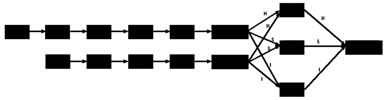
[0025] Such as figure 1 As shown, it is a schematic flowchart of the method for fast wavelet fusion of thermal imaging images and optical images of fast-moving objects according to the present invention. A fast wavelet fusion method for thermal imaging images and optical images of fast moving objects, comprising the following steps:

[0026] A. Acquire thermal imaging images and optical images of fast-moving objects, and preprocess thermal imaging images and optical images respectively;

[0027] B, decomposing the thermal imaging image and optical image after step A preprocessing into tone image,...


PUM


Abstract

The invention discloses a fast wavelet fusion method for fast moving object thermal imaging image and optical image, which includes preprocessing thermal imaging image and optical image, HSI decomposing thermal imaging image and optical image, wavelet decomposition processing, wavelet fusion processing and wavelet reconstruction processing to obtain fused image. As that thermal image and the optical image are HSI decomposed, The decomposition layers are fused by wavelet fusion method, which can effectively synthesize the thermal imaging image target characteristic information and optical imagescene details information, and obtain more comprehensive information fusion image, so as to realize the effective imaging of fast moving objects.

Description

technical field [0001] The invention belongs to the technical field of image processing, and in particular relates to a fast wavelet fusion method of thermal imaging images and optical images of fast moving objects. Background technique [0002] Due to the various limitations of the sensor's own physical characteristics, imaging mechanism, and viewing angle, a single image sensor is often unable to extract enough information from the scene, so that it is difficult or even impossible to obtain a comprehensive description of a scene independently. Thermal imaging images and visible light images are obtained through thermal imaging sensors and visible light imaging sensors respectively. Since the principles of the two sensors are different, their performances are also different. Thermal imaging images can better reflect the thermal target characteristics of the image, but are not sensitive to scene brightness changes, and the image clarity is low; visible light images can bette...

Claims


Application Information

Patent Timeline
IPC IPC(8): G06T5/50G06T5/40G06T5/10
CPCG06T5/10G06T5/40G06T5/50G06T2207/10048G06T2207/10052G06T2207/20064G06T2207/20221
Inventor 周利明
Owner CHENGDU KNIGHT TECH
Why Eureka
Try Eureka