A Large-Range Variable Orbit Magnet Structure for Continuous Beam Acceleration

A large-scale, orbital technology, applied in the direction of magnetic resonance accelerators, accelerators, electrical components, etc., can solve the problems of beam extraction energy limitation, beam energy improvement, etc., to improve focusing intensity, avoid divergence, and break through the extraction of beam current The effect of energy restriction

Active Publication Date: 2019-10-15
CHINA INSTITUTE OF ATOMIC ENERGY
View PDF9 Cites 0 Cited by
  • Summary
  • Abstract
  • Description
  • Claims
  • Application Information

AI Technical Summary

Problems solved by technology

[0005] Aiming at the deficiencies of the prior art, the present invention proposes a large-scale variable-orbit magnet assembly structure for continuous beam acceleration, aiming to solve the problems of traditional cyclotron beam energy enhancement and beam extraction energy limitation

Method used


Image

  • A Large-Range Variable Orbit Magnet Structure for Continuous Beam Acceleration
  • A Large-Range Variable Orbit Magnet Structure for Continuous Beam Acceleration
  • A Large-Range Variable Orbit Magnet Structure for Continuous Beam Acceleration

Examples


Embodiment

[0044] In this embodiment, the relationship between the magnetic air gap and the radius is as attached Figure 6 As shown, the relationship between the magnetic field curve and the radius is as Figure 7 shown.

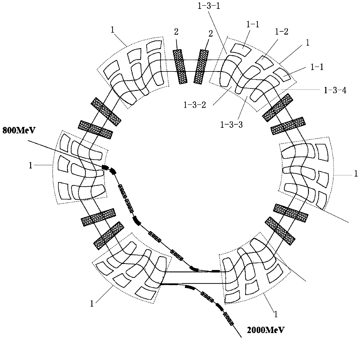
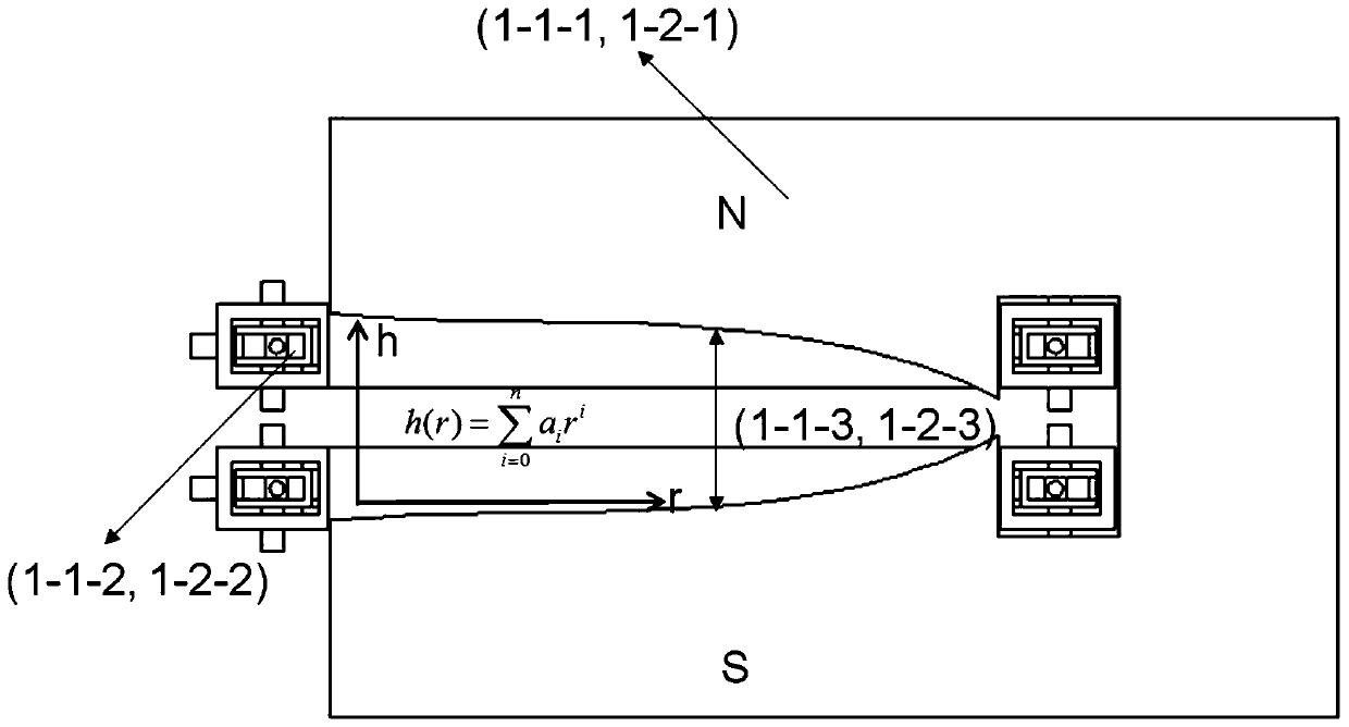
[0045] This embodiment can realize the constrained proton beam injected from 800MeV and accelerated to 2GeV magnet assembly structure in the way of continuous beam acceleration. Among them, the average radii of the beam orbits of 800MeV and 2GeV are 16.28 meters and 18.33 meters respectively. The minimum field strength of the defocused magnet is 0.59 Tesla, the highest field strength is 2.48 Tesla, the magnet width is 1.82 meters, the half-height of the magnetic air gap at the widest point in the radial direction is 25 mm, and the half-height of the central magnetic air gap is 188.62 mm.

[0046] The orbit change refers to that as the energy of the beam continues to increase, the radius of the orbit that the beam runs also increases continuously. The change in the r...


PUM


Abstract

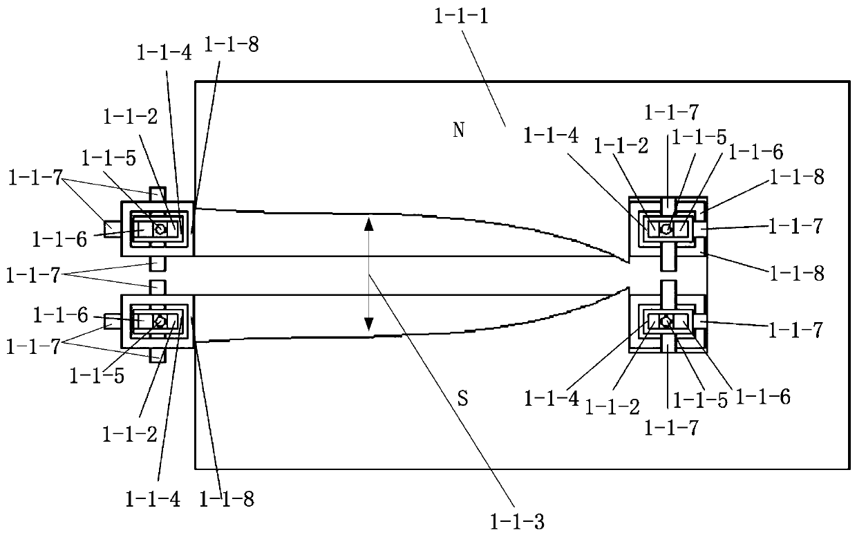
The invention discloses a wide-range orbital transfer magnet structure realizing continuous beam acceleration. The magnet structure is used for forming magnetic components of a circular accelerator, the magnetic components periodically generate twisting orbits and are arranged along the peripheral direction of the accelerator at intervals, each magnetic component comprises two magnets which are deflected forwards and radially focused and one magnet which is reversely deflected and axially focused, and the wide-range orbital transfer magnet structure comprises a magnetic pole structure, a magnetic air gap structure and a magnet exciting coil. The wide-range orbital transfer magnet structure is characterized in that the magnetic air gap structure of the magnet structure is a large-radius range air gap varying magnetic air gap structure. By the aid of the large-radius range air gap varying magnetic air gap structure which is characterized in that the space distance between an upper magnetic pole and a lower magnetic pole is shortened along with lengthening of the magnetic pole radius of the accelerator, namely, by the aid of the magnet structure which meets a higher-degree polynomialrelation between the space distance h between the upper magnetic pole and the lower magnetic pole and the magnetic pole radius r, and the magnet structure solves the problem that beam energy led out by a traditional circular accelerator is lower than 1GeV.

Description

technical field [0001] The invention belongs to the technical field of accelerator magnets, in particular to a large-range track-changing magnet structure for realizing continuous beam acceleration. Background technique [0002] Among the high-power proton accelerators, the cyclotron scheme, the combination scheme of the linear accelerator and the fast cycle synchrotron are two schemes widely recognized internationally. The advantage of the cyclotron scheme is that it adopts the continuous beam acceleration method, the average current is strong, the equipment scale is relatively small, and the cost is low. The disadvantage is that when the beam energy is high, the maximum extraction energy of the beam is generally below 1GeV due to insufficient focusing force. , thus limiting the further increase of cyclotron power. The advantage of the combination scheme of linear accelerator and fast cycle synchrotron is that it can greatly increase the extraction energy of the beam, whic...

Claims


Application Information

Patent Timeline
Patent Type & Authority Patents(China)
IPC IPC(8): H05H7/04H05H13/00
Inventor 王川李明边天剑安世忠张天爵
Owner CHINA INSTITUTE OF ATOMIC ENERGY
Why Eureka
Try Eureka