
Multifunctional agricultural spraying machine

A sprayer and multi-functional technology, applied in the field of multi-functional agricultural sprayers, can solve the problems of unreachable range and spray effect, blind spray, insufficient hydraulic pressure, etc., to achieve automatic operation, improve spraying range and ensure uniformity Effect

Inactive Publication Date: 2019-02-22
NANTONG SCI & TECH VOCATIONAL COLLEGE
View PDF0 Cites 0 Cited by
  • Summary
  • Abstract
  • Description
  • Claims
  • Application Information

AI Technical Summary

Problems solved by technology

[0002] At present, the spraying of pesticides on trees is mostly done by using the pump to supply the spray gun with high-pressure liquid spray through the rubber hose. If the spray gun produces a large amount of liquid per unit time, it will easily cause insufficient hydraulic pressure and fail to achieve the ideal range and spray effect. Therefore, it is not possible to use large spray holes or multiple Nozzle spray gun
In tree spraying, the drug pump is usually used to supply one or two spray guns to spray the trees continuously. This continuous spraying method to the trees is prone to partial re-spraying and blind spraying when pulling the rubber hose, especially when carrying out tree trunks. When fully spraying, the sprayer needs to operate around the trunk, which is time-consuming and labor-intensive, and wastes the liquid medicine
At present, some trees are sprayed with mist spraying machines, but because many urban trees grow on the side of the road, the spraying of mist spraying machines will affect passers-by on the roadside, so it is not suitable for urban construction trees

Method used


Image

  • Multifunctional agricultural spraying machine
  • Multifunctional agricultural spraying machine
  • Multifunctional agricultural spraying machine

Examples


Embodiment Construction

[0018] The following will clearly and completely describe the technical solutions in the embodiments of the present invention with reference to the accompanying drawings in the embodiments of the present invention. Obviously, the described embodiments are only some, not all, embodiments of the present invention. Based on the embodiments of the present invention, all other embodiments obtained by persons of ordinary skill in the art without making creative efforts belong to the protection scope of the present invention.

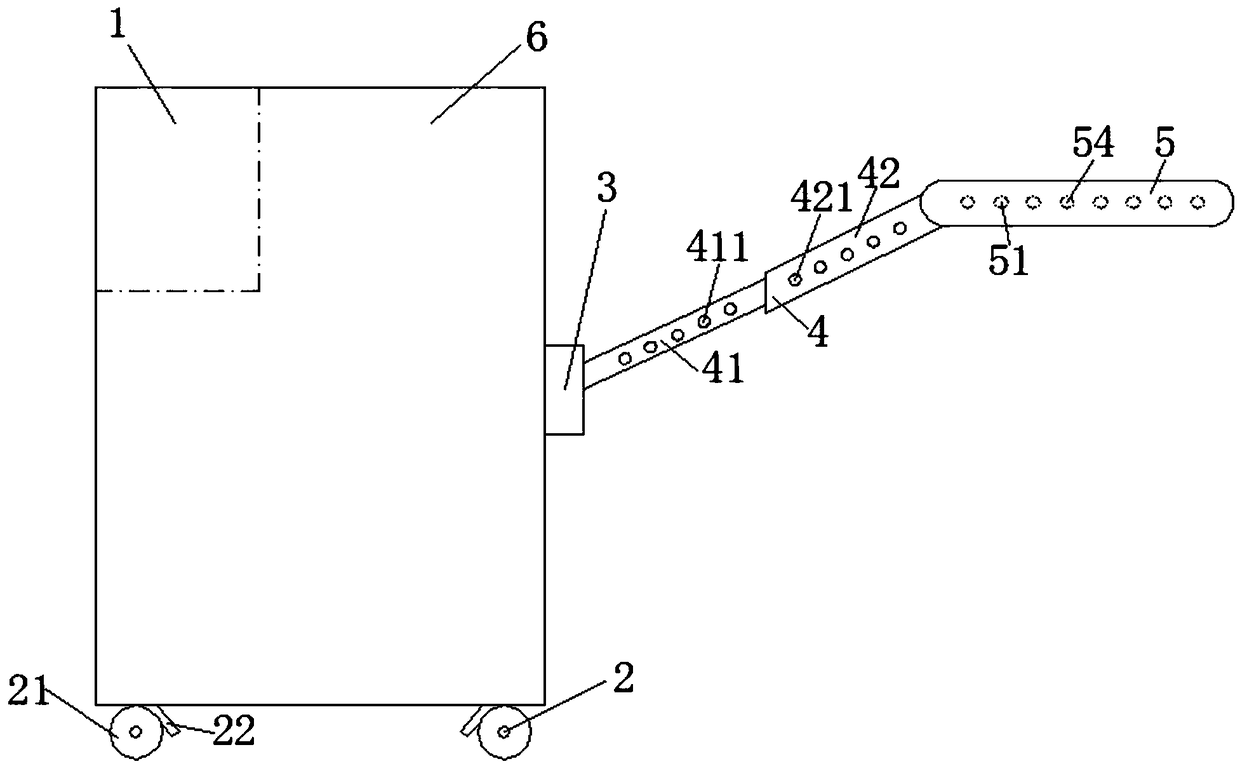
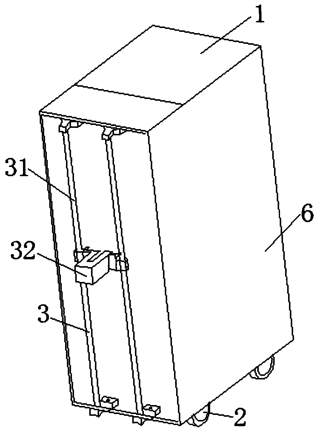
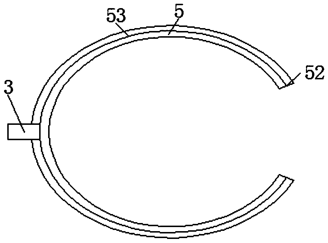
[0019] Such as Figure 1-3 As shown, a multifunctional agricultural sprayer includes a box body 6, a pressure sprayer 1, a running mechanism 2, a connecting mechanism 3, a telescopic support 4 and an annular nozzle 5, the pressure sprayer 1 is installed at the inner end of the box body 6, and the running mechanism 2 is fixedly installed on the bottom end of the box body 6, the connecting mechanism 3 is fixedly installed on one side of the outer end of the box ...


PUM


Abstract

The invention discloses a multifunctional agricultural spraying machine. The machine comprises a box body, a pressure spraying device, a walking mechanism, a connecting mechanism, a telescopic supporting frame and an annular nozzle, the pressure spraying device is installed at the inner end of the box body, the walking mechanism is fixedly installed at the bottom of the box body, the connecting mechanism is fixedly installed on one side of the outer end of the box body, the telescopic supporting frame is connected with the box body through the connecting mechanism, and the annular nozzle is fixedly installed at the front end of the telescopic supporting frame. According to the spraying machine, by adopting the special structure of the annular nozzle, the annular nozzle sleeves the outer surface of a tree trunk, 360-degree all-direction spraying is conducted on the tree trunk, and therefore the uniformity of pesticide spraying is ensured. By adopting a lead screw and a driving motor, the up-and-down controlling over the annular nozzle is achieved, the automatic operation of the annular nozzle is achieved, the convenience of operation is greatly improved, and labor force is saved.

Description

technical field [0001] The invention relates to the field of sprayers, in particular to a multifunctional agricultural sprayer. Background technique [0002] At present, the spraying of pesticides on trees is mostly carried out by using the chemical pump to supply the spray gun with high-pressure liquid spraying through the rubber hose. If the spray gun produces a large amount of liquid per unit time, it will easily cause insufficient hydraulic pressure and fail to achieve the ideal range and spray effect. Therefore, it is not possible to use large spray holes or multiple Orifice spray gun. In tree spraying, one or two spray guns are usually supplied by the medicine pump to spray the trees continuously. This continuous spraying method for trees is prone to partial re-spraying and blind spraying when pulling the rubber hose, especially when carrying out tree trunk spraying. When fully spraying, the applicators need to operate around the trunk, which is time-consuming and lab...

Claims


Application Information

Patent Timeline
IPC IPC(8): A01M7/00
CPCA01M7/0042A01M7/005A01M7/0089
Inventor 郑兴国沈素香周小林吴军
Owner NANTONG SCI & TECH VOCATIONAL COLLEGE
Learn More