Device for auxiliary fixing
A technology of positioning member and support frame, applied in the direction of catheter, etc., can solve the problems of easy falling off of injection, easy sliding injection point, myocardial wall wear, etc., to prevent damage or even puncture, reduce the difficulty of surgical operation, and increase stability. Effect
- Summary
- Abstract
- Description
- Claims
- Application Information
AI Technical Summary
Problems solved by technology
Method used
Image
Examples
Embodiment 1
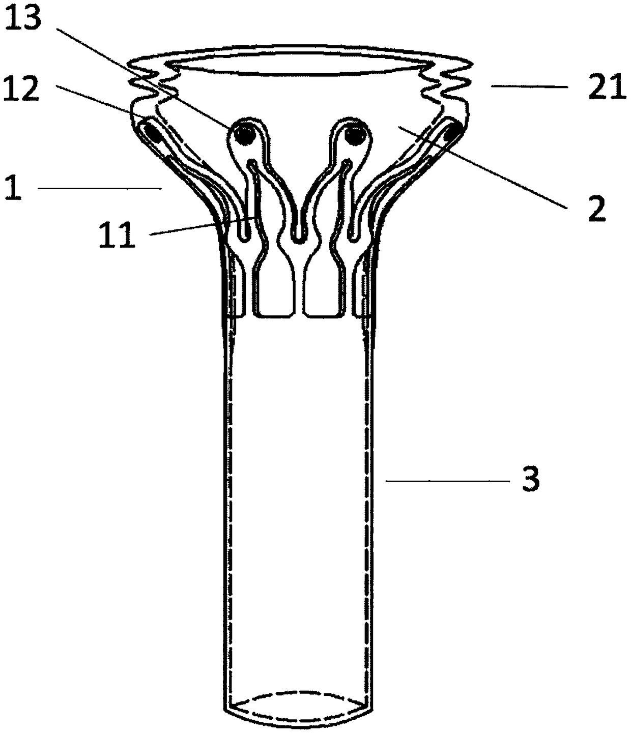
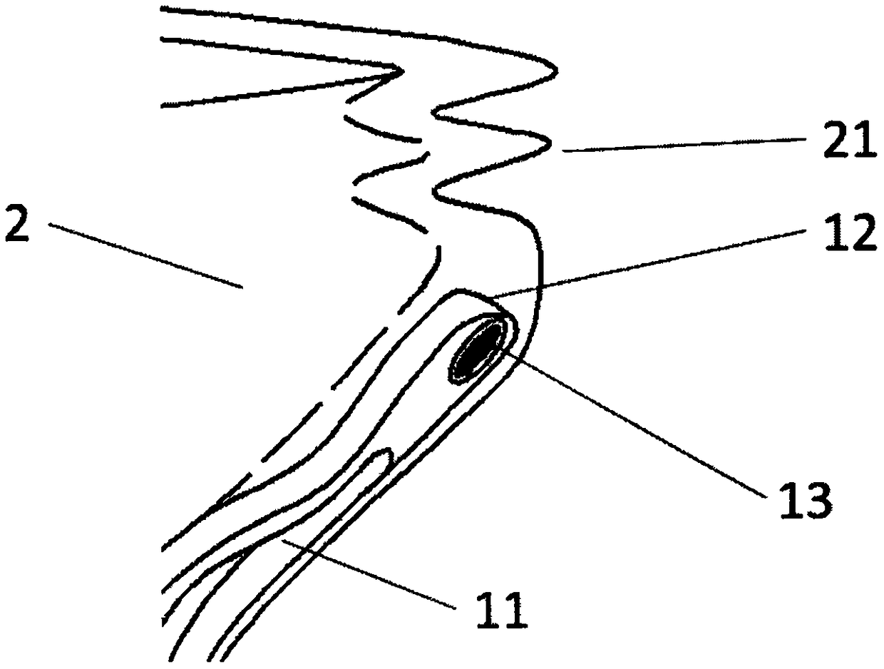
[0055] see Figure 1a As shown, a device for auxiliary fixation provided by the present invention includes a support frame 1, a membrane structure 2 and a connecting piece 3, the distal part of the support frame 1 is in an open state, and the support frame 1 is composed of multiple The support rod 11 is composed of a support rod 11, the distal part of the support rod 11 is provided with a puncture-proof structure 12, the membrane structure 2 is fixedly connected to the support frame 1, and the distal part of the membrane structure 2 is provided with a reinforcing structure 21 , the connecting piece 3 is fixedly connected to the proximal end of the support frame 1, and the inside of the connecting piece 3 is hollow. This embodiment is suitable for injecting into the intracardiac surface of the ventricular wall to treat heart failure diseases.
[0056] Such as Figure 1a As shown, the support frame 1 is trumpet-shaped, the number of the support rods 11 is 2-40, and the support...
Embodiment 2
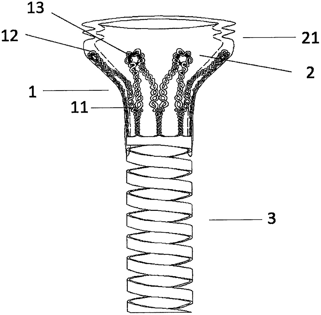
[0065] see figure 2 As shown, the structure of a device for auxiliary fixation in this embodiment is basically the same as that in Embodiment 1, the difference is that in this device in this embodiment, the reinforcing structure 21 is specifically an annular strip The reinforcement structure 21 is located at the distal end of the membrane structure 2, and expands outward along the membrane structure 2, and can be axially compressed along the midline of the support frame 1. The reinforcing structure 21 can be made of biocompatible polymer film, such as PU, PTFE, PET, PE, silica gel or one or more materials. At the same time, the trumpet-shaped reinforcing structure 21 can prevent the distal end of the support frame 1 from piercing into the inner wall of the left ventricle and cause damage. In addition, it can also make the device play a supporting role when vacuuming, and the distal end of the reinforcing structure is fastened to the ventricle wall. On the other hand, the vac...
Embodiment 3
[0067] The difference between this embodiment and Embodiment 1 is that, as Figures 11a to 11c As shown, the anti-puncture structure 12 is a structure that extends radially outward along the support rod 11 and gradually bends toward the proximal end of the support frame 1, and the curved sections of the support rod 11 are respectively point-supported on the tissue surface Above, the anti-puncture structures 12 are evenly arranged along the circumferential direction of the support frame 1, and the number of the anti-puncture structures 12 is at least three. The angle β between the tangent line at the end of the anti-puncture structure 12 and the central axis of the device is ≥90°. Such as Figure 11d As shown, the anti-puncture structure 12 cooperates with the inner wall 7 of the ventricle after unfolding, so that the anti-puncture structure 12 can extend along the inner wall 7 of the ventricle, so that the distal end of the anti-puncture structure 12 will not pierce the inner...
PUM
 Abstract
Description
Claims
Application Information
 - R&D
- Intellectual Property
- Life Sciences
- Materials
- Tech Scout
- Unparalleled Data Quality
- Higher Quality Content
- 60% Fewer Hallucinations
Browse by: Latest US Patents, China's latest patents, Technical Efficacy Thesaurus, Application Domain, Technology Topic, Popular Technical Reports.
© 2025 PatSnap. All rights reserved.Legal|Privacy policy|Modern Slavery Act Transparency Statement|Sitemap|About US| Contact US: help@patsnap.com


