
Cloth clip cutter plate surface cleaning device for setting machine

A technology of cleaning device and setting machine, which is applied in the direction of using tools for cleaning, cleaning methods and utensils, chemical instruments and methods, etc. The effect of sizing cloth sticking, improving production efficiency and reducing the strength of brushing

Pending Publication Date: 2019-02-22
JIANGSU LITTLE SUN TECH DEV CO LTD
View PDF0 Cites 0 Cited by
  • Summary
  • Abstract
  • Description
  • Claims
  • Application Information

AI Technical Summary

Problems solved by technology

When printing and dyeing enterprises use cloth clips to process part of the sizing cloth, the wet slurry at the cloth inlet will stick to the surface of the cloth clips, and will be cured after being heated in the drying room of the setting machine, resulting in uneven surface of the blades and affecting the cloth clips. Accuracy, resulting in the phenomenon of fabric stripping when clamping cloth
At present, printing and dyeing enterprises have no better solution besides manual pulp removal

Method used


Image

  • Cloth clip cutter plate surface cleaning device for setting machine
  • Cloth clip cutter plate surface cleaning device for setting machine

Examples


Embodiment 1

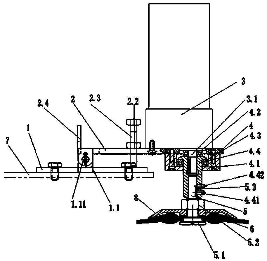
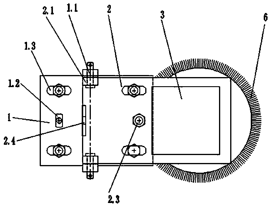
[0021] Embodiment 1: as figure 1 As shown, a device for cleaning the surface of a cloth clip knife for a shaping machine includes a mounting base 1, a connecting bracket 2, an electric deceleration motor 3, a bearing assembly 4, a dowel 5, and a brush wheel 6. The mounting base 1 is connected to the On the cover plate 7 at the outer semicircle of the machine tail; one end of the connecting bracket 2 is connected to the installation base 1, and the other end extends out of the cover plate 7 at the outer semicircle of the shaping machine tail; the connecting bracket 2 extends out of the outer semicircle of the shaping machine tail One end of the cover plate 7 at the place is provided with a through hole, the electric deceleration motor 3 is fixed above the connecting bracket 2 and the output shaft 3.1 of the electric decelerating motor 3 passes through the through hole; the bearing assembly 4 is fixed under the connecting bracket 2, the bearing assembly 4 and the output The shaf...


PUM


Abstract

The invention provides a cloth clip cutter plate surface cleaning device for a setting machine. The cloth clip cutter plate surface cleaning device is characterized in that the device comprises an installation base, a connection bracket, an electric gear motor, a bearing assembly, a dowel bar and a brush wheel; the installation base is connected to a cover plate located at the semicircle positionof the outer side of the tail of the setting machine; one end of the connection bracket is connected to the installation base, and the other end of the connection bracket stretches out of the cover plate located at the semicircle position of the outer side of the tail of the setting machine; one end, stretching out of the cover plate located at the semicircle position of the outer side of the tailof the setting machine, of the connection bracket is provided with a through hole, the electric gear motor is fixed to the upper portion of the connection bracket, and an output shaft of the electricgear motor penetrates the through hole; the bearing assembly is fixed to the lower portion of the connection bracket and is in transmission connection with the output shaft; the dowel bar is connected to the lower portion of the bearing assembly; and the brush wheel is connected to the bottom of the dowel bar. Through the cloth clip cutter plate surface cleaning device, the problem that filled cloth adheres to a clip can be effectively solved, and normal working of the setting machine is not influenced when the cloth clip cutter plate surface cleaning device conducts cleaning work.

Description

technical field [0001] The invention relates to the technical field of textile machinery and equipment, in particular to a cloth clip blade surface cleaning device for a setting machine. Background technique [0002] At present, the stenter setting machine is widely used in the finishing process of various textiles such as knitted fabrics and woven fabrics. According to the processing technology of the printing and dyeing factory, some fabrics need to be edged. When printing and dyeing enterprises use cloth clips to process part of the sizing cloth, the wet slurry at the cloth inlet will stick to the surface of the cloth clips, and will be cured after being heated in the drying room of the setting machine, resulting in uneven surface of the blades and affecting the cloth clips. Accuracy, resulting in fabric clipping and other phenomena when clamping cloth. At present, printing and dyeing enterprises do not have a better solution except manual pulp removal. Contents of the...

Claims


Application Information

Patent Timeline
Patent Type & Authority Applications(China)
IPC IPC(8): B08B1/00B08B1/02B08B13/00
CPCB08B13/00B08B1/20B08B1/12
Inventor 张才南张盛周燕钱祖勤
Owner JIANGSU LITTLE SUN TECH DEV CO LTD
Learn More