Cleaning device for producing electronic controller of automobile engine

A technology for electronic controllers and automobile engines, which is applied to the cleaning method using tools, the cleaning method using liquid, and the cleaning method using gas flow, etc. The effect of expanding the scope of work

Inactive Publication Date: 2019-02-22
柳州英飞科技有限公司
View PDF0 Cites 8 Cited by
  • Summary
  • Abstract
  • Description
  • Claims
  • Application Information

AI Technical Summary

Problems solved by technology

[0003] With the rapid popularization of automobiles, the output requirements for auto parts are also increasing, and the cleaning devices for the production of electronic controllers for automobile engines are becoming more and more important. The existing cleaning devices on the market have beautiful appearance and novel styles. , low cost and easy maintenance. However, when the cleaning device for the production of automotive engine electronic controllers is used, it often cleans a working surface of a material. After the work is completed, the material is turned over or selected for the next step. The cleaning of a working surface has a small working range and cumbersome procedures, which seriously reduces the working efficiency. Therefore, a cleaning device for the production of electronic controllers of automobile engines is proposed to solve the above problems.

Method used


Image

  • Cleaning device for producing electronic controller of automobile engine
  • Cleaning device for producing electronic controller of automobile engine
  • Cleaning device for producing electronic controller of automobile engine

Examples


Embodiment Construction

[0025] The following will clearly and completely describe the technical solutions in the embodiments of the present invention with reference to the accompanying drawings in the embodiments of the present invention. Obviously, the described embodiments are only some, not all, embodiments of the present invention.

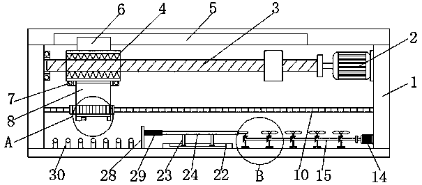
[0026] refer to Figure 1-5, a cleaning device for the production of automotive engine electronic controllers, comprising a mounting frame 1, a driving motor 2 is fixedly connected to the inner right side wall of the mounting frame 1, a supporting plate is fixedly connected to the internal right side wall of the mounting frame 1, and the supporting plate The left side wall of the drive motor 2 is fixedly connected to the purpose of protecting the drive motor 2 and prolonging the service life of the drive motor 2. The output end of the drive motor 2 is fixedly connected with a threaded rod 3, and the outer surface of the threaded rod 3 is threaded. Sleeve 4, the cross...


PUM


Abstract

The invention discloses a cleaning device for producing an electronic controller of an automobile engine. The cleaning device includes a mounting frame, wherein a drive motor is fixedly connected withthe inner right side wall of the mounting frame; the output end of the drive motor is fixedly connected with a threaded rod; the outer surface of the threaded rod is connected with a threaded sleevein a thread mode; a sliding trough is formed on the inner top wall of the mounting frame; a slider is movably connected with the inside of the sliding trough; the upper surface of the threaded sleeveis fixedly connected with the slider; and a first bearing is fixedly connected with the lower surface of the threaded sleeve. Through the arrangement of the drive motor, when the cleaning device is used, the drive motor drives the threaded sleeve to move rightwards along the sliding trough through the threaded rod; the threaded sleeve drives a gear ring to move along a rack through a mounting table; the rack meshes with the gear ring, so that the mounting table drives materials to rotate; the materials can be cleaned and processed in multiple directions; the problems of replacing and cleaningworking surfaces are solved; and the purpose of expanding the working range is achieved.

Description

technical field [0001] The invention relates to the technical field of engine electronic controllers, in particular to a cleaning device for the production of automobile engine electronic controllers. Background technique [0002] The car engine is the device that provides power for the car. It is the heart of the car and determines the power, economy, stability and environmental protection of the car. According to different power sources, car engines can be divided into diesel engines, gasoline engines, and electric car motors. As well as hybrid power, common gasoline engines and diesel engines are reciprocating piston internal combustion engines, which convert the chemical energy of fuel into mechanical energy of piston motion and output power externally. Gasoline engines have high speed, low mass, low noise, easy starting, and low manufacturing costs. , The diesel engine has a large compression ratio, high thermal efficiency, economic performance and emission performance ...

Claims


Application Information

Patent Timeline
Patent Type & Authority Applications(China)
IPC IPC(8): B08B3/02B08B1/00B08B5/02
CPCB08B3/022B08B1/006B08B1/008B08B5/023
Inventor 陈红姬
Owner 柳州英飞科技有限公司
Why Eureka
Try Eureka