
An automatic collection device for floating garbage used in shallow sea and coastal waters

A near-shore water area and automatic collection technology, which is applied to the cleaning of open water surfaces, water conservancy projects, construction, etc., can solve the problems of low energy consumption and investment, high energy consumption, low efficiency, etc., and achieve simple structure, pollution reduction, and control and pollution effects

Inactive Publication Date: 2020-11-24
郝泽青
View PDF7 Cites 0 Cited by
  • Summary
  • Abstract
  • Description
  • Claims
  • Application Information

AI Technical Summary

Problems solved by technology

[0002] With the rise of the marine economy and the gradual improvement of people's environmental requirements, marine pollution, especially offshore pollution, has received more and more attention. Complex, the current governance policies and methods are mainly based on the control of imported pollution from fixed sources in the watershed, such as the adoption of environmental management measures currently being implemented in my country, such as improving the discharge standards of land-based point source and line source pollution; but for non-fixed Natural runoff and other natural and human-input pollution are basically powerless, such as runoff caused by rainfall, wind, non-point source pollution, tourism, and shipping sewage, etc.
Some countries use low-efficiency, high-energy-consumption power boats for manual cleaning or cleaning ships for mechanical cleaning, and some countries use large-scale tow pipes / nets for collection and transportation, which is a short-term solution for serious and relatively concentrated pollution. The control is very effective, but for the situation where the floating garbage is relatively scattered, the terrain is complex, the amount of pollutants is not very large and long-term control is required, its energy consumption and investment are very inefficient compared to pollution reduction

Method used


Image

  • An automatic collection device for floating garbage used in shallow sea and coastal waters
  • An automatic collection device for floating garbage used in shallow sea and coastal waters
  • An automatic collection device for floating garbage used in shallow sea and coastal waters

Examples


Embodiment Construction

[0015] Below in conjunction with specific embodiment, further illustrate the present invention.

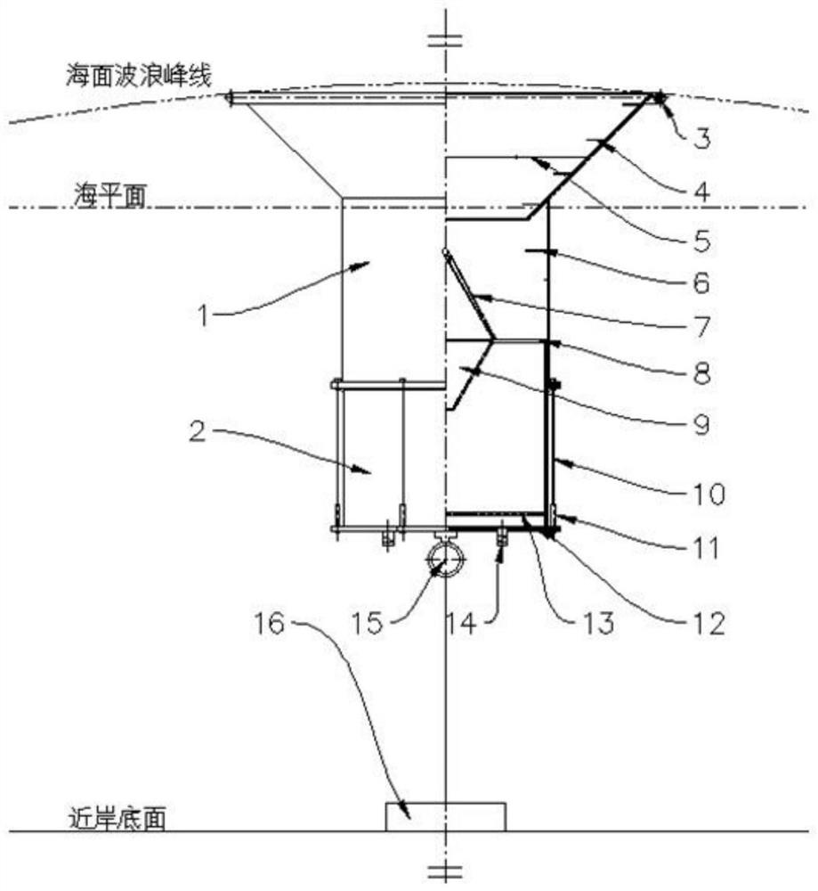
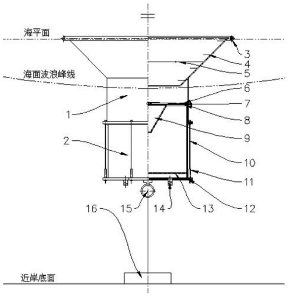
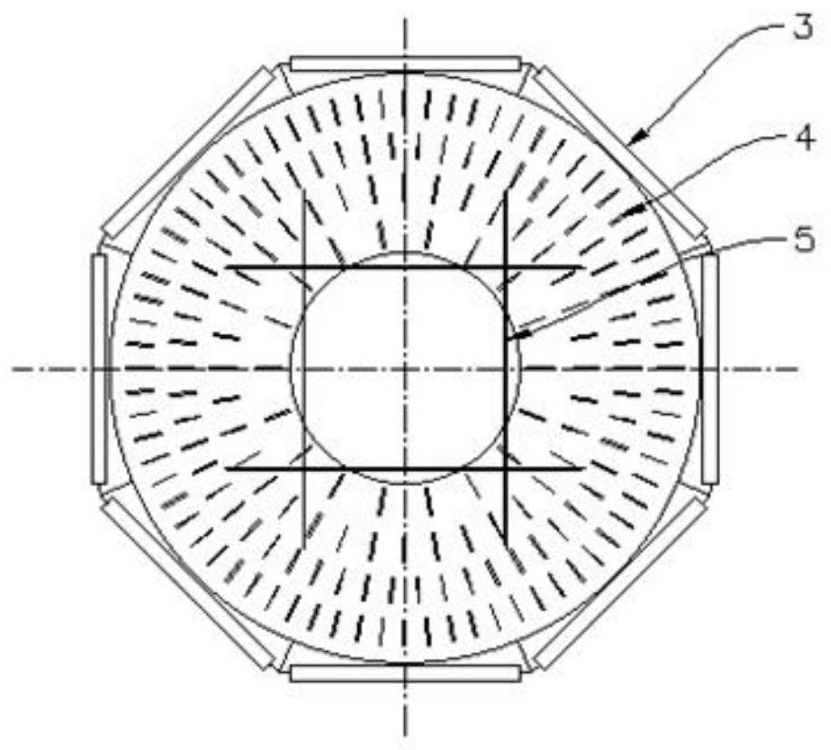
[0016] An automatic collection device for floating garbage used in shallow sea and coastal waters of the present invention is mainly composed of an upper floating cylinder 1 and a lower fixed cylinder 2. The upper floating cylinder is funnel-shaped to increase buoyancy and stability, and the edge is provided with rotating rollers. 3. In order to facilitate the flexible floating garbage to enter the upper floating cylinder, a fixed protrusion 4 is provided inside the funnel of the upper floating cylinder 1 to prevent the floating objects entering the upper floating cylinder 1 from moving outward during the up and down movement of the upper floating cylinder 1; grid layer 5 On the one hand, it plays a strengthening role, and on the other hand, it can prevent oversized floating objects from entering the bottom of the upper floating cylinder 1. The bottom of the upper floating cylinde...


PUM


Abstract

The invention relates to a floating rubbish automatic collecting device for shallow sea near-shore water areas. The device is characterized by comprising an upper part floating cylinder and a lower part fixing cylinder which are floating on the sea surface; and the upper part floating cylinder can move up and down relative to the lower part fixing cylinder, the lower part fixing cylinder is used for positioning in the sea through a positioning device, a movable door is arranged on one side of the lower portion of the upper part floating cylinder, a plurality of fixing protruding parts are arranged inside the upper part floating cylinder, and a one-way drainage valve is arranged at the bottom of the lower part fixing cylinder. The device is simple in structure, is the unpowered and movableshallow sea floating rubbish automatic collecting device, and can effectively control and alleviate the floating rubbish pollution of the ocean.

Description

technical field [0001] The invention relates to an automatic collection device for floating garbage used in shallow sea and coastal waters. Background technique [0002] With the rise of the marine economy and the gradual improvement of people's environmental requirements, marine pollution, especially offshore pollution, has received more and more attention. Complex, the current governance policies and methods are mainly based on the control of imported pollution from fixed sources in the watershed, such as the adoption of environmental management measures currently being implemented in my country, such as improving the discharge standards of land-based point source and line source pollution; but for non-fixed Natural runoff and other natural and human-input pollution are basically powerless, such as runoff caused by rainfall, wind power, non-point source pollution, tourism, and shipping sewage. Some countries use low-efficiency, high-energy-consumption power boats for manual...

Claims


Application Information

Patent Timeline
Patent Type & Authority Patents(China)
IPC IPC(8): E02B15/10
CPCE02B15/10
Inventor 郝泽青
Owner 郝泽青
Learn More