Compressor
A technology for compressors and compression chambers, applied in the field of compressors, can solve problems such as wear of the movable scroll, failure of the pump body to fit tightly, leakage, etc., to ensure the sealing of the pump body and avoid the wear and tear of the back of the movable scroll Effect
- Summary
- Abstract
- Description
- Claims
- Application Information
AI Technical Summary
Problems solved by technology
Method used
Image

Examples
Embodiment 1
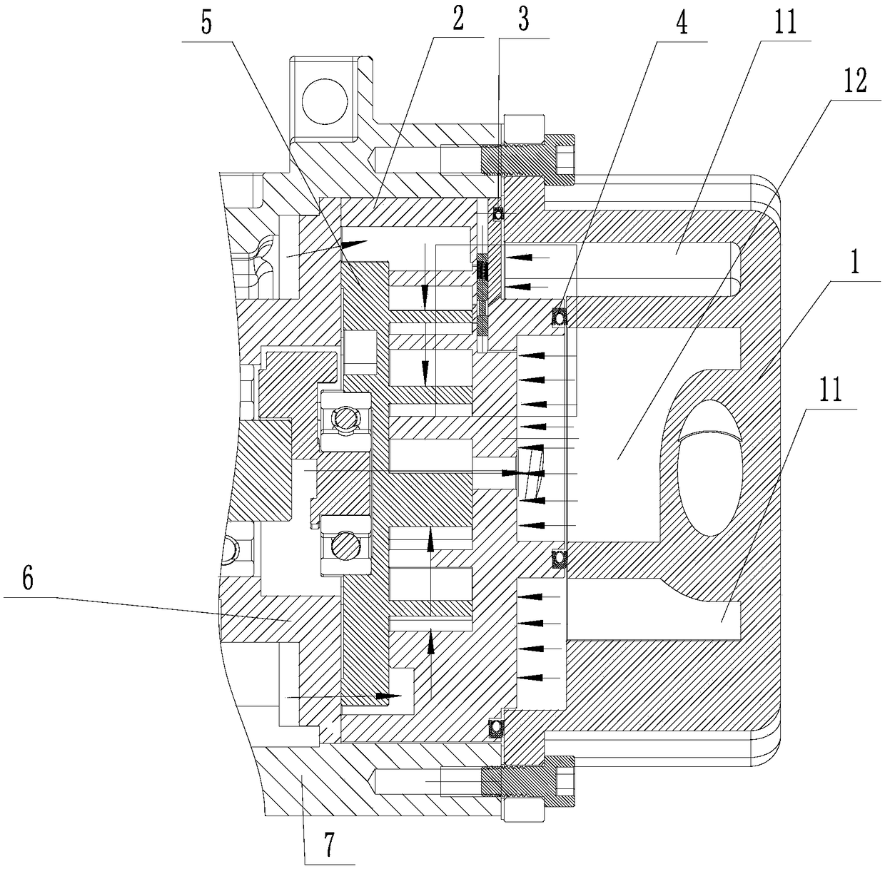
[0033] combined with Figure 1-3 As shown (the direction of the arrow in the figure is the airflow direction), this embodiment provides a compressor, including: head cover 1, fixed scroll 2, movable scroll 5, bracket assembly 6, casing 7, etc. part.
[0034] The casing 7 of this embodiment is connected with the machine head cover 1 to form a cavity, and an air intake cavity is formed in the cavity; the fixed scroll 2, the movable scroll 5 and the bracket assembly of this embodiment 6 is installed in the casing 7, wherein the movable scroll 5 is installed between the fixed scroll 2 and the bracket assembly 6, and a part of the fixed scroll 2 can abut against the movable scroll 5, and the movable scroll A part of the rotating disk 5 can abut against the support assembly 6 , and the movable scroll 5 can float between the fixed scroll 2 and the support assembly 6 along the left-right direction in the figure.
[0035] The compression chamber of this embodiment is formed between t...
Embodiment 2
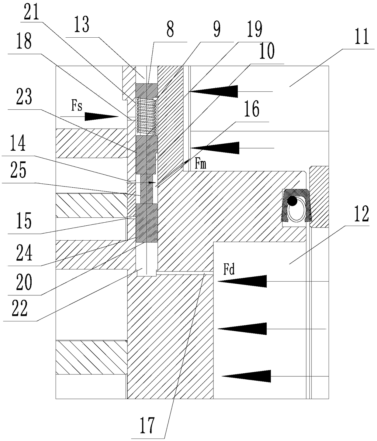
[0047] The only difference between this embodiment and Embodiment 1 is that the structural form of the adjustment mechanism is different. Figure 4-6 As shown, the adjustment channel 13 of this embodiment is the same as that of the above-mentioned embodiment, so its specific structure will not be described in this embodiment.
[0048] Specifically, the regulating valve of this embodiment includes a valve body 10 and a pressure regulating member; both ends of the valve body 10 and the regulating channel 13 respectively form a first space 21 and a second space 22, and the pressure regulating member communicates with the first space 21 and the second space respectively. Two spaces 22, and by adjusting the pressure of the first space 21 and the second space 22, the valve body 10 moves in the adjustment channel 13 to control the first exhaust hole 16 and the first back pressure hole 14 / second back pressure hole 15.
[0049] Specifically, the valve body 10 of this embodiment includ...
Embodiment 3
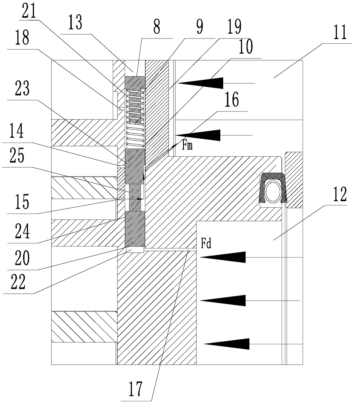
[0052] The only difference is that the structural form of the adjustment mechanism is different, combined with the attached Figure 7-9 As shown, the adjustment channel 13 of this embodiment is the same as that of the above-mentioned embodiment, so its specific structure will not be described in this embodiment.
[0053] Specifically, the regulating valve of this embodiment includes a coil 29, a plunger 8, an elastic member 9 and a valve body 10, wherein the plunger 8, the elastic member 9 and the valve body 10 are connected in sequence, and the coil 29 is sleeved outside the elastic member 9 The plunger 8 is fixedly installed in the regulating channel 13 and is tightly connected with the regulating channel 13; the coil 29 can absorb the valve body 10 by turning on and off the power, so that the valve body 10 can move in the regulating channel 13 to control the conduction of the valve body 10. A vent hole 16 and the first back pressure hole 14 / the second back pressure hole 1...
PUM
 Abstract
Description
Claims
Application Information
 - R&D
- Intellectual Property
- Life Sciences
- Materials
- Tech Scout
- Unparalleled Data Quality
- Higher Quality Content
- 60% Fewer Hallucinations
Browse by: Latest US Patents, China's latest patents, Technical Efficacy Thesaurus, Application Domain, Technology Topic, Popular Technical Reports.
© 2025 PatSnap. All rights reserved.Legal|Privacy policy|Modern Slavery Act Transparency Statement|Sitemap|About US| Contact US: help@patsnap.com