Complex part pose estimation system and method based on three-dimensional measuring point cloud

A technology for complex parts and three-dimensional measurement, which is applied in the direction of measuring devices, instruments, and optical devices, can solve the problems of robot measuring point planning deviation, robot measuring system collision, and large randomness, so as to avoid measurement point cloud splicing errors, Solve pose problems and measure a wide range of effects

Active Publication Date: 2019-02-22
HUAZHONG UNIV OF SCI & TECH
View PDF7 Cites 29 Cited by
  • Summary
  • Abstract
  • Description
  • Claims
  • Application Information

AI Technical Summary

Problems solved by technology

The traditional workpiece pose estimation method includes manual alignment method, which relies on manual operation, is random and inaccurate; there is also the method of using visual positioning to obtain the pose of the workpiece, which uses the characteristics of the workpiece to perform image matching to obtain Workpiece pose, this method is not suitable for workpieces with inconspicuous features, and the calculation is complicated
[0003] These traditional measurement methods are not only complicated, but also difficult to obtain accurate workpiece poses, resulting in deviations in subsequent path planning, especially when the workpiece is very large, it is very difficult to obtain the workpiece coordinate system, which will lead to subsequent robots. There are large deviations in the planning of measuring points, which may lead to unexpected collisions between the robot measuring system and the external environment

Method used


Image

  • Complex part pose estimation system and method based on three-dimensional measuring point cloud
  • Complex part pose estimation system and method based on three-dimensional measuring point cloud
  • Complex part pose estimation system and method based on three-dimensional measuring point cloud

Examples


Embodiment Construction

[0032] In order to make the object, technical solution and advantages of the present invention clearer, the present invention will be further described in detail below in conjunction with the accompanying drawings and embodiments. It should be understood that the specific embodiments described here are only used to explain the present invention, not to limit the present invention. In addition, the technical features involved in the various embodiments of the present invention described below can be combined with each other as long as they do not constitute a conflict with each other.

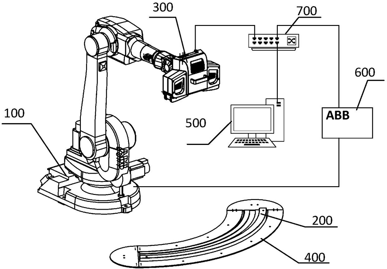
[0033] Such as figure 1 As shown, an embodiment of the present invention provides a complex part pose estimation system based on a three-dimensional measurement point cloud, which includes a six-degree-of-freedom industrial robot 100, a measured workpiece 200, a raster type area scanner 300, and a support frame for marker points 400 and data processing host computer 500.

[0034] The end of th...


PUM


Abstract

The invention belongs to the field of automatic measurement and specifically discloses a complex part pose estimation system and method based on three-dimensional measuring point cloud. The method forestimating a complex part pose comprises a step of calibrating a conversion matrix between a six-degree-of-freedom industrial robot end flange and a grating area array scanner measurement coordinatesystem, a step of driving a grating area array scanner to move through the six-degree-of-freedom industrial robot to scan a measured workpiece and obtaining three-dimensional point cloud data of the measured workpiece, a step of converting the three-dimensional point cloud data of the measured workpiece to a robot base coordinate system to obtain converted three-dimensional point cloud data, and astep of matching the converted three-dimensional point cloud data with a three-dimensional design model of the measured workpiece to obtain the pose of the measured workpiece relative to the robot soas to complete the estimation of the pose of a complex part. The invention has a wide measurement range, the accurate measurement of multiple regions and complete topography of the measured workpiececan be achieved, and the pose of the measured workpiece can be accurately obtained.

Description

technical field [0001] The invention belongs to the field of automatic measurement, and more specifically relates to a system and method for estimating the pose of a complex part based on a three-dimensional measurement point cloud. Background technique [0002] Robot 3D automatic measurement needs to plan a complete and collision-free path, and the path planning must know the attitude of the workpiece relative to the robot's base coordinate system. The traditional workpiece pose estimation method includes manual alignment method, which relies on manual operation, is random and inaccurate; there is also a method of using visual positioning to obtain the pose of the workpiece, which uses the characteristics of the workpiece to perform image matching to obtain Workpiece pose, this method is not suitable for workpieces with inconspicuous features, and the calculation is complex. [0003] These traditional measurement methods are not only complicated, but also difficult to obta...

Claims


Application Information

Patent Timeline
Patent Type & Authority Applications(China)
IPC IPC(8): G01B11/00
CPCG01B11/002
Inventor 李文龙胡著王刚田亚明
Owner HUAZHONG UNIV OF SCI & TECH
Why Eureka
Try Eureka