Test device for simulating horizontal earthquake effect bearing by cross-shaped beam-column joint

A beam-column joint and test device technology is applied in the field of civil engineering to achieve the effects of reducing column bottom slip, large friction coefficient and increasing frictional force

Pending Publication Date: 2019-02-22
HUNAN UNIV OF TECH
View PDF7 Cites 2 Cited by
  • Summary
  • Abstract
  • Description
  • Claims
  • Application Information

AI Technical Summary

Problems solved by technology

[0004] In the prior art, the research on the hysteretic performance of beam-column joints mainly adopts structural pseudo-static load tests, which can simulate the seismic performance of joint specimens under earthquake action. However, most of the pseudo-static tests adopt The loading method is column end loading, and the pseudo-static test of column end loading mainly studies the plastic hinge at the end of the column. The aseismic performance of the joint under the action of an earthquake cannot be fully demonstrated from a single aspect of the end of the column.

Method used


Image

  • Test device for simulating horizontal earthquake effect bearing by cross-shaped beam-column joint
  • Test device for simulating horizontal earthquake effect bearing by cross-shaped beam-column joint
  • Test device for simulating horizontal earthquake effect bearing by cross-shaped beam-column joint

Examples


Embodiment 1

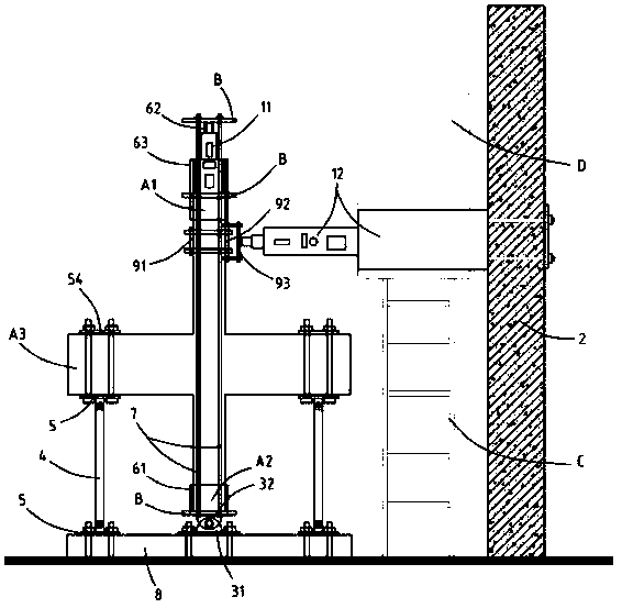
[0040] Such as figure 1 As shown, there is provided a test device for simulating a cross-shaped beam-column joint bearing horizontal earthquake action, including an axial compression loading device 11 that can apply pressure at the top of the beam-column joint specimen, and can place the beam-column joint specimen above the beam. A reciprocating loading device 12 for applying horizontal force on the side of the column end, and a fixing frame 2 for fixing the reciprocating loading device; wherein, the column bottom A2 of the beam-column node specimen is hinged to the ground through hinges, and a vertical Arranged connecting rod 4, the two ends of the connecting rod 4 are respectively hinged with the beam end A3 and the ground through the hinge seat 5; it also includes the first sleeve 61 for setting the column bottom A2, and the contact with the free end of the axial pressure loading device 11 The second sleeve 62, the third sleeve 63 covering the intersection of the column top...


PUM


Abstract

The invention, which belongs to the field of civil engineering, discloses a test device for simulating a horizontal earthquake effect bearing by a cross-shaped beam-column joint. The test device comprises a shaft stress loading device for applying pressures on a test piece column top, a reciprocating loading device for applying a horizontal force on the side of a column end, and a fixation frame for fixing the reciprocating loading device. The bottom of the test piece column is hinged to the ground by a hinging piece; connecting rods arranged vertically are arranged between the beam end and the ground; and the two ends of the connecting rods are hinged to the beam end and the ground respectively by hinge bases. In addition, the test device also includes a first sleeve sleeving the column bottom, a second sleeve in contact with a free end of the shaft pressure loading device, and a third sleeve coating the connection part between the column top and the shaft stress loading device; the third sleeve has a structure with two open ends, one open end coats the periphery of the column top, and the other open end coats the periphery of the shaft stress loading device; a separation board isarranged between the two open ends and is in contact with the test piece column top; and the three sleeves are connected into one by connecting pieces. With the test device, the stable axial stress ratio is realized; and the actual condition of bearing the horizontal earthquake effect by the beam-column joint is reflected truly.

Description

technical field [0001] The invention relates to the technical field of civil engineering, in particular to a test device for simulating a cross-shaped beam-column joint bearing horizontal earthquake action. Background technique [0002] The frame structure not only has the advantages of flexible layout, good structural integrity and good rigidity, but also has good seismic performance, and also has the advantages of light weight, less consumables, and short construction period. [0003] The beam-column joint refers to the joint core area, the beam end near the joint core area and the column end near the joint core area in the frame structure. It is an important force transmission hub in the frame structure, which can transmit and distribute internal forces. Generally, it is more complex than beams, columns, and plate members, and the shear force it bears is about 4 to 6 times that of the column. Frame joints are the weakest part of the frame structure, and the damage of the...

Claims


Application Information

Patent Timeline
Patent Type & Authority Applications(China)
IPC IPC(8): G01M7/02
CPCG01M7/02G01M7/022
Inventor 蒋隆敏唐从青何深育李如博
Owner HUNAN UNIV OF TECH
Why Eureka
Try Eureka