Optical film defect laser damage threshold test method

A laser damage threshold and optical thin film technology, applied in the field of optical detection, can solve problems such as difficulty in ensuring the accuracy of optical thin films, achieve high applicability and improve test accuracy.

Active Publication Date: 2019-02-22
中国工程物理研究院上海激光等离子体研究所
View PDF6 Cites 11 Cited by
  • Summary
  • Abstract
  • Description
  • Claims
  • Application Information

AI Technical Summary

Problems solved by technology

[0002] Optical thin films are widely used in high-power laser systems, but the laser damage of optical thin films has always been a bottleneck limiting its development
For optical thin films, the electric field distribution is mainly modulated by the film structure, and the electric field intensities suffered by defects at different depths in optical thin films are also different, and the international standard laser damage threshold test method also does not affect the defects in optical thin films. Analysis of the influence of the electric field on the damage
[0004] Since the existing laser damage threshold test method is difficult to guarantee the accuracy of the damage threshold test for optical film defects, it is necessary to invent a defect damage threshold test method for optical films under long-pulse laser irradiation

Method used


Image

  • Optical film defect laser damage threshold test method
  • Optical film defect laser damage threshold test method
  • Optical film defect laser damage threshold test method

Examples


Embodiment Construction

[0036] The following will clearly and completely describe the technical solutions in the embodiments of the present invention with reference to the accompanying drawings in the embodiments of the present invention. Obviously, the described embodiments are only some, not all, embodiments of the present invention. Based on the embodiments of the present invention, all other embodiments obtained by persons of ordinary skill in the art without making creative efforts belong to the protection scope of the present invention.

[0037]In describing the present invention, it should be understood that the terms "longitudinal", "transverse", "upper", "lower", "front", "rear", "left", "right", "vertical", The orientation or positional relationship indicated by "horizontal", "top", "bottom", "inner", "outer", etc. are based on the orientation or positional relationship shown in the drawings, and are only for the convenience of describing the present invention and simplifying the description...


PUM


Abstract

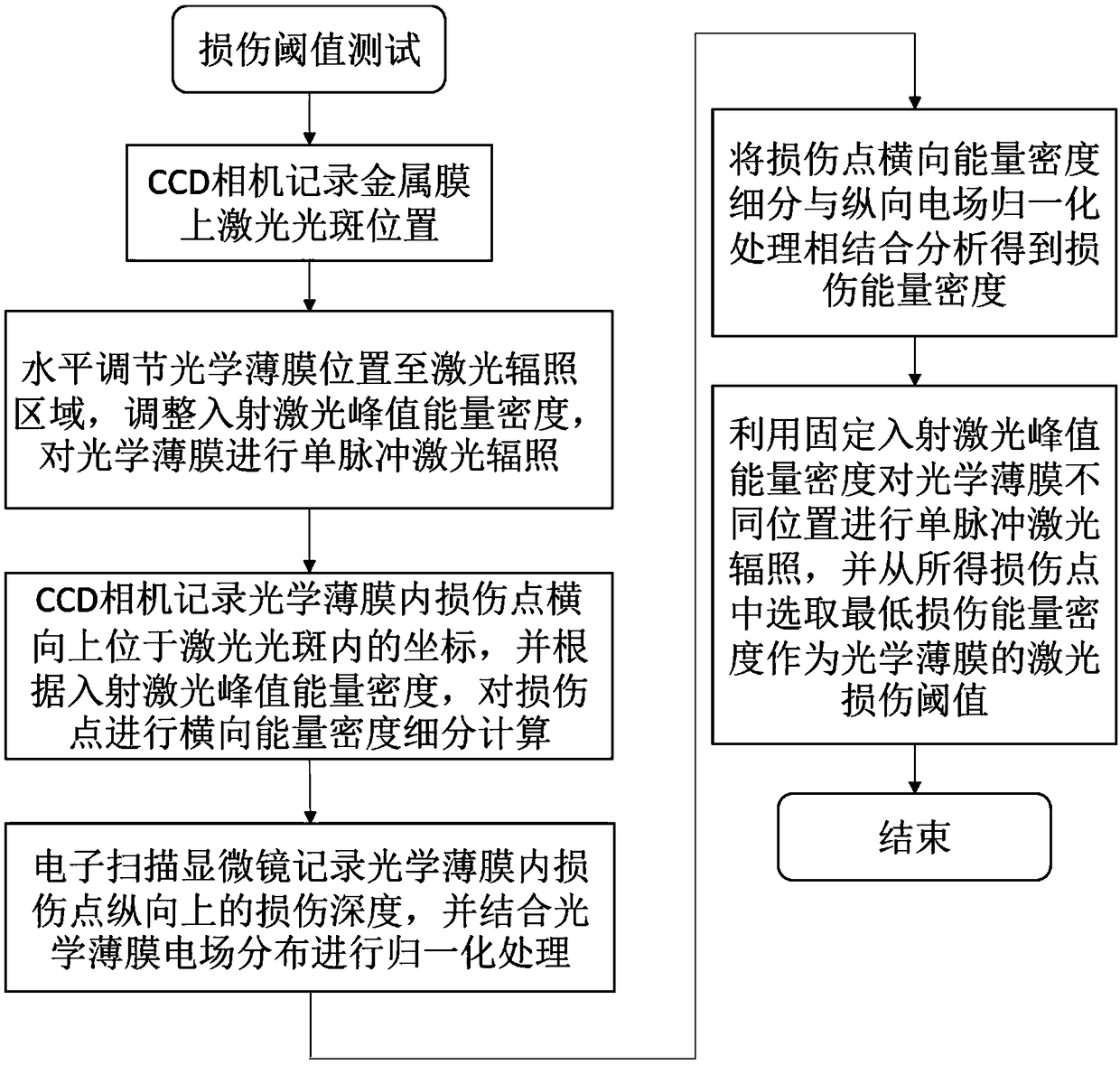
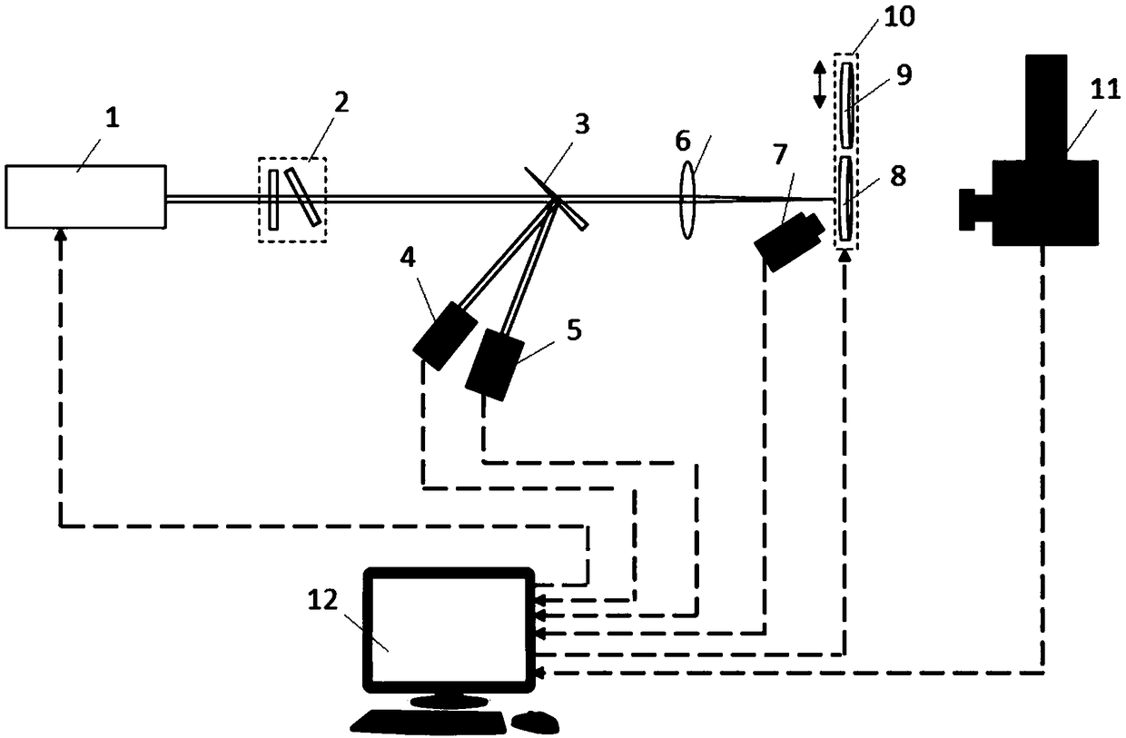
The invention discloses an optical film defect laser damage threshold test method. According to the method, after a laser beam passes through an attenuator and arrives at a beam splitter, and the laser beam in the transmission direction of the beam splitter passes through a focusing lens and arrives at a metal film; a CCD camera records a spot position where the laser irradiates on the surface ofthe metal film and a laser damage point coordinate where the laser irradiates on the surface of the optical film; and a scanning electron microscope records the longitudinal depth position of the defect damage point of the optical film in the irradiation of the laser and completes a defect damage point lateral energy density subdivision and longitudinal electric field normalization processing-combined analysis. In an optical film defect laser damage threshold test in the prior art, randomly-distributed defect damage points and laser energy density of Gaussian distribution in a laser spot are considered to be uniformly-distributed damage points and laser energy density equivalently, and influence on the defect damage point caused by the electric field distribution of the optical film is ignored, and as a result, many problems are brought about, while with the optical film defect laser damage threshold test method of the invention adopted, the above problems can be solved, and test accuracy can be improved.

Description

technical field [0001] The invention belongs to the field of optical detection, in particular to a method for testing the laser damage threshold of optical film defects. Background technique [0002] Optical thin films are widely used in high-power laser systems, but the laser damage of optical thin films has always been a bottleneck limiting their development. An accurate laser damage threshold not only provides a safe range of use for optical films, but also a prerequisite for research on how to improve their resistance to laser damage. [0003] Under long-pulse laser irradiation, the laser damage of optical films is mainly caused by the defects in the optical films, and the laser damage threshold caused by defects is much smaller than the laser damage threshold corresponding to intrinsic damage. However, the international standard laser damage threshold test method regards the uneven distribution of defect damage as equivalent to the Gaussian distribution of laser energy...

Claims


Application Information

Patent Timeline
Patent Type & Authority Applications(China)
IPC IPC(8): G01M11/02
CPCG01M11/00
Inventor 单翀赵元安高妍琦赵晓晖崔勇饶大幸刘佳妮胡国行马伟新
Owner 中国工程物理研究院上海激光等离子体研究所
Why Eureka
Try Eureka