
A light guide plate, a manufacturing method of the light guide plate, a backlight module, and a display device

A technology for a backlight module and a manufacturing method, which is applied in the directions of light guides, optics, and optical components, can solve problems such as uneven surface light sources, and achieve the effects of improving light output, enhancing display uniformity, and improving brightness.

Active Publication Date: 2020-07-31
XIAMEN TIANMA MICRO ELECTRONICS
View PDF13 Cites 0 Cited by
  • Summary
  • Abstract
  • Description
  • Claims
  • Application Information

AI Technical Summary

Problems solved by technology

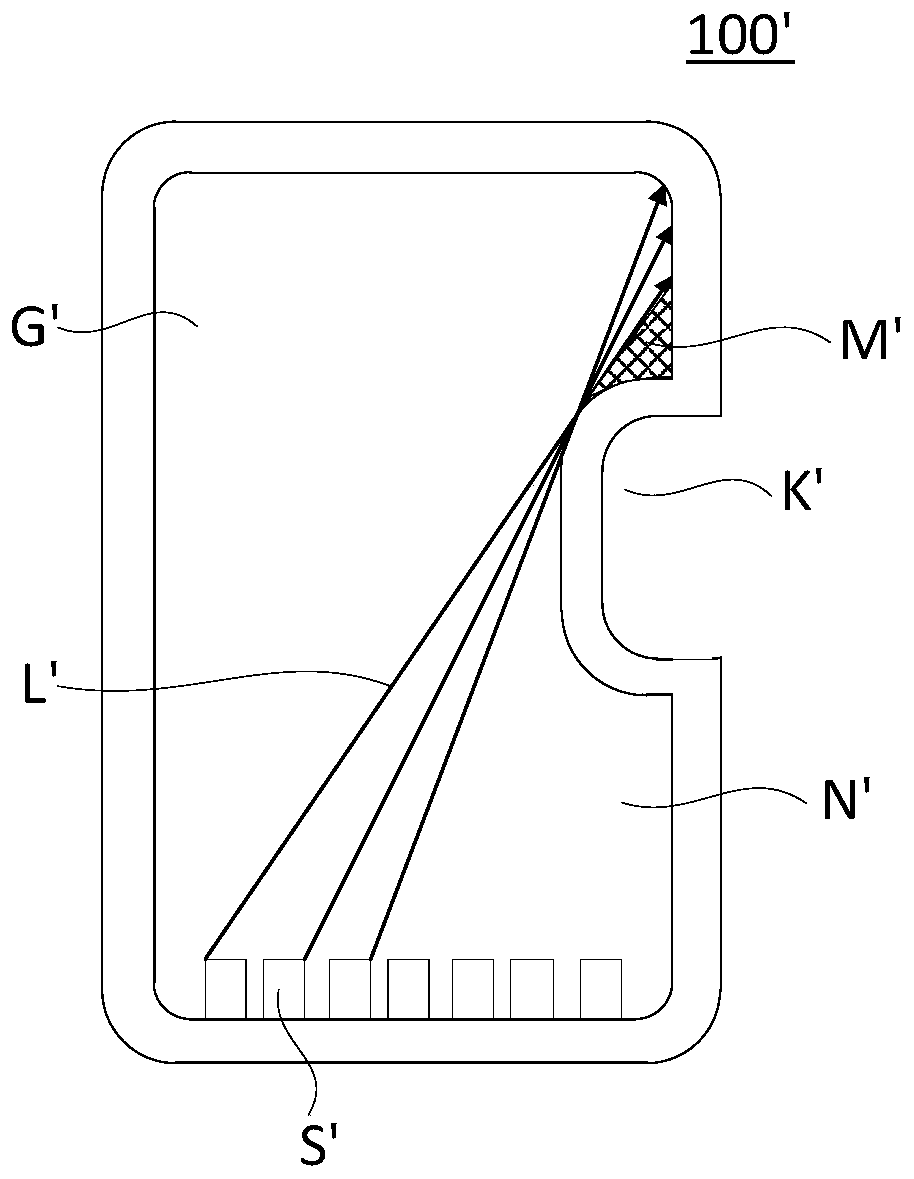
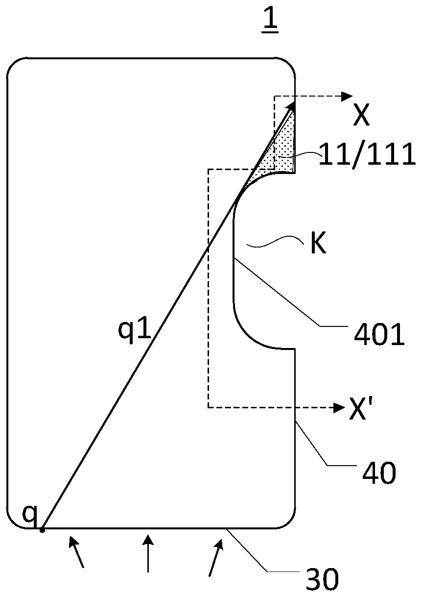
[0004] In view of this, the present invention provides a light guide plate, a manufacturing method of the light guide plate, a backlight module, and a display device, which are used to improve the problem of non-uniform surface light sources caused by the opening design of the light guide plate, and realize the side-in type backlight The brightness of the dark area of ​​the light guide plate in the module is improved to enhance the display effect of the display panel

Method used


Image

  • A light guide plate, a manufacturing method of the light guide plate, a backlight module, and a display device
  • A light guide plate, a manufacturing method of the light guide plate, a backlight module, and a display device
  • A light guide plate, a manufacturing method of the light guide plate, a backlight module, and a display device

Examples


Embodiment Construction

[0029] In order to better understand the technical solutions of the present invention, the embodiments of the present invention will be described in detail below in conjunction with the accompanying drawings.

[0030] It should be clear that the described embodiments are only some of the embodiments of the present invention, not all of them. Based on the embodiments of the present invention, all other embodiments obtained by persons of ordinary skill in the art without making creative efforts belong to the protection scope of the present invention.

[0031] The following description of at least one exemplary embodiment is merely illustrative in nature and in no way taken as limiting the invention, its application or uses.

[0032] Techniques, methods and devices known to those of ordinary skill in the relevant art may not be discussed in detail, but where appropriate, such techniques, methods and devices should be considered part of the description.

[0033] In order to impro...


PUM


Abstract

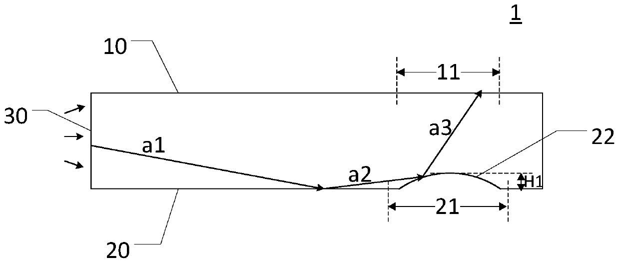
The invention provides a light guide plate, a manufacturing method thereof, a backlight module set and a display device and belongs to the technical field of display. The light guide plate comprises afirst light guiding region; the first light guiding region is located at one side of a groove structure, wherein the one side of the groove structure is far away from a light incident surface. A reflection surface includes a first reflection region; the first reflection region comprises at least one protruding structure; the protruding structure is at least partially overlapped with the orthographic projection of the first light guiding region at the light guide plate. The protruding structure is arranged on the reflection surface corresponding to the first light guiding region, so that it can be ensured that light reflected by the first reflection region can go out from the first light guiding region as much as possible, and therefore, the light extraction rate of the reflected light ofthe first reflection region at the first light guiding region can be improved, and therefore, the brightness of the first light guiding region can be compensated, and the brightness of the first lightguiding region of the light guide plate of a side-lit backlight module can be improved, and the uniformity of the display brightness of a display panel can be enhanced.

Description

technical field [0001] The invention relates to the field of display technology, in particular to a light guide plate, a manufacturing method of the light guide plate, a backlight module and a display device. Background technique [0002] A liquid crystal display device usually includes a backlight module and a liquid crystal display panel. When the liquid crystal display panel displays images, the backlight source in the backlight module needs to provide light to realize normal display of the display device. The backlight includes direct-type backlight and side-type backlight. The side-type backlight is arranged on the side of the light guide plate, and provides a uniform surface light source for the display panel through the special reflection of the reflective surface of the light guide plate. [0003] At the same time, with the development of display technology, heterosexual display panels have attracted more and more attention due to their larger screen-to-body ratio. A...

Claims


Application Information

Patent Timeline
Patent Type & Authority Patents(China)
IPC IPC(8): G02B6/00G02F1/13357
CPCG02B6/0035G02B6/0055G02B6/0065G02F1/133615
Inventor 洪金龙
Owner XIAMEN TIANMA MICRO ELECTRONICS
Learn More