Dimming cylinder for debugging galvanometer coaxial core and debugging method

A coaxial, dimming technology, applied in optics, optical components, instruments, etc., can solve the problems of height deviation, large distance of the galvanometer, and inability to determine the installation position, and achieve the effect of simple and reasonable structure and good practical effect.

Pending Publication Date: 2019-02-22
WUHAN GSTAR TECH CO LTD
View PDF0 Cites 4 Cited by
  • Summary
  • Abstract
  • Description
  • Claims
  • Application Information

AI Technical Summary

Problems solved by technology

At present, when assembling the mounting parts of the galvanometer, generally there will be a height deviation in the left-right direction or the front-rear direction, but there is no reference benchmark, and it is impossible to determine whether the installation position has reached its ideal horizontal position after assembly
Moreover, the distance between the oscillating head and the surface of the adsorption platform of the processed workpiece is relatively large

Method used


Image

  • Dimming cylinder for debugging galvanometer coaxial core and debugging method
  • Dimming cylinder for debugging galvanometer coaxial core and debugging method
  • Dimming cylinder for debugging galvanometer coaxial core and debugging method

Examples


Embodiment 1

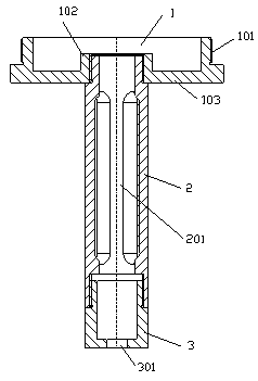
[0030] Such as figure 1 , 2 , As shown in 3 and 4, a dimmer tube for debugging the galvanometer coaxial center, including a dimmer connection cover 1, a dimmer adapter tube 2, and a dimmer joint 3, and a dimmer connection cover 1 is provided with a field lens to cooperate with The connected external thread structure 101 has a central boss 102 in the center, and is connected as a whole through a flange cover 103; The dimming joint 3 is provided with a dimming hole 301, and is connected to the lower end of the dimming socket 2; the outer thread structure 101 and the center of the dimming hole 301 are coaxially set.

[0031] Optimally, the interior of the central boss 102 is provided with an internal thread coaxial with the external thread structure 101. Correspondingly, the upper end of the dimming socket 2 is provided with an external thread, and is connected to the dimming connection cover 1 through a thread pair. Together; similarly, the lower end of the dimming adapter 2 i...

Embodiment 2

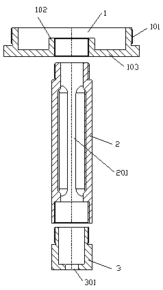
[0034] Such as Figure 5 As shown: a dimmer tube for adjusting the galvanometer coaxial center, the difference from the first embodiment is: optimized, the dimmer receiver 2 and the dimmer connection cover 1 are fixedly connected to form an integrated structure; The lower end of 2 is provided with a coaxial internal thread, and correspondingly, the upper end of the dimming joint 3 is provided with an external thread, and is connected with the dimming socket 2 through a pair of threads.

[0035] With such an arrangement, the internal thread at the lower end of the dimming connector 2 can be processed on the same positioning basis as the external thread structure 101 on the dimming connection cover 1 to ensure a high-precision coaxial center, thereby further improving the brightness of the dimming connector 3. The concentricity between the small dimming hole 301 and the external thread structure 101 is determined.

Embodiment 3

[0037] Such as Figure 6 As shown, a dimmer tube for debugging the concentric center of the vibrating mirror is different from Embodiment 1 in that: optimized, the dimmer connector 3 and the dimmer receiver 2 are fixedly connected to form an integrated structure; the dimmer receiver 2 Correspondingly, the center boss 102 is provided with an internal thread coaxial with the external thread structure 101, and is connected with the dimming socket 2 through a thread pair.

[0038] With such a setting, the dimming small hole 301 on the dimming joint 3 is coaxially processed with the external thread on the upper end of the dimming receiver 2 to ensure high-precision coaxiality, thereby further ensuring that the dimming small hole 301 and the external thread The concentricity of the structure 101.


PUM


Abstract

The invention discloses a dimming cylinder for debugging galvanometer coaxial core. The dimming cylinder comprises a dimming connection cover, a dimming connection tube and a dimming joint connected to each other. The dimming connection cover is provided with an external thread structure, a central boss and a flange cover. The dimming connection tube is in the shape of a slender cylinder and is internally provided with a light guiding through hole. The dimming joint is provided with a dimming small hole. The external thread structure and the center of the dimming small hole are coaxially arranged. The debugging method comprises the steps of (a) removing a field lens, (b) rotating the external thread structure of the dimming connection cover onto a standard internal thread of the field lens, (c) placing a frequency doubling sheet directly under the dimming joint and allowing laser to form observable green light, (d) switching on an optical system switch, (e) allowing the laser to project onto the frequency doubling sheet to form a green ring band, (f) observe the coaxiality of an inner ring and an outer ring of the ring band and finely adjusting the left and right and front and rear horizontal positions of galvanometer mounting parts, and (g) resetting parameters to adjust again. The dimming cylinder has a simple structure, the debugging method is simple and easy to operate, and the practical effect is good.

Description

technical field [0001] The invention relates to a debugging auxiliary tool for debugging the coaxial center of a vibrating mirror on a laser device, in particular to a light adjusting cylinder and a debugging method for debugging the coaxial center of a vibrating mirror. Background technique [0002] At present, in laser processing equipment, the laser path of the optical path system often passes through multiple components, and the installation position of the intermediate components will directly affect the concentricity of the optical path. In order to ensure that the laser can act vertically on the surface of the processed workpiece through the galvanometer, it is necessary to determine its concentricity with the laser path when assembling the galvanometer mounting parts. At present, when assembling the mounting parts of the galvanometer, generally there will be a height deviation in the left-right direction or the front-rear direction, but there is no reference benchmar...

Claims


Application Information

Patent Timeline
Patent Type & Authority Applications(China)
IPC IPC(8): G02B27/62
CPCG02B27/62
Inventor 陈刚袁聪林少辉
Owner WUHAN GSTAR TECH CO LTD
Why Eureka
Try Eureka