A high-impedance crystal resonator series oscillation circuit and its debugging method

A technology of crystal resonators and oscillation circuits, applied in power oscillators, electrical components, etc., can solve the problem of accurate compensation of static capacitance C0, which affects the frequency stability of crystal resonators, and cannot effectively control the amplitude of the excitation voltage of crystal resonators and other problems, to achieve the effect of stable excitation amplitude, simple debugging method, and low noise amplification

Active Publication Date: 2017-10-27
BEIJING RES INST OF TELEMETRY +1
View PDF1 Cites 0 Cited by
  • Summary
  • Abstract
  • Description
  • Claims
  • Application Information

AI Technical Summary

Problems solved by technology

[0005] The commonly used Butler circuit is a typical crystal resonator series oscillating circuit. This circuit realizes the compensation of the static capacitance C0 by connecting an inductor in parallel with the crystal resonator. However, due to the actual application process, the size of the static capacitance C0 Affected by many factors such as electrode leads, package base, and circuit board welding methods, it is difficult to achieve accurate compensation for static capacitance C0 only by connecting fixed inductance in parallel, and it is impossible to ensure that the crystal resonator works in a series resonance state; at the same time, the The method cannot effectively control the amplitude of the excitation voltage of the crystal resonator, which affects the frequency stability of the crystal resonator
[0006] In the document "Phase noise analysis of the FrequencyTracking Oscillator", the French Space Agency (ONERA) proposed an oscillation circuit including a static capacitance C0 compensation unit. This circuit is based on the principle of a phase-locked loop and can be used for excitation of high-impedance crystal resonators. , but only the circuit block diagram and basic working principle are given in the literature, and its specific implementation form and debugging method are not given

Method used


Image

  • A high-impedance crystal resonator series oscillation circuit and its debugging method
  • A high-impedance crystal resonator series oscillation circuit and its debugging method
  • A high-impedance crystal resonator series oscillation circuit and its debugging method

Examples


Embodiment Construction

[0032] Below in conjunction with accompanying drawing and specific embodiment the present invention is described in further detail:

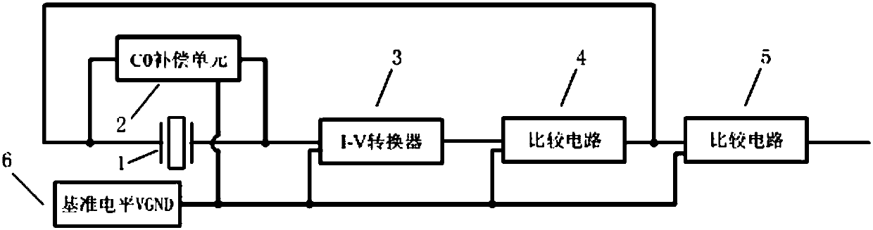
[0033] Such as figure 1 Shown is a schematic structural diagram of the oscillating circuit of the present invention. It can be seen from the figure that the circuit includes a high-impedance crystal resonator 1, a C0 compensation unit 2, an I / V converter 3, a first comparison circuit 4, a second comparison circuit 5, a reference voltage Ping VGND6. Among them, the impedance Z of the high-impedance crystal resonator 1 is 10 in the resonant state 5 A crystal resonator above the Ω level, but it can still be other conventional crystal resonators; the two ends of the C0 compensation unit 2 are respectively connected to the two ends of the high-impedance crystal resonator 1, and the high-impedance crystal resonator 1 can be statically adjusted through simple debugging. The compensation of capacitance C0 ensures that the high-impedance crystal resona...


PUM


Abstract

The invention discloses a high-impedance crystal resonator serial oscillating circuit. The high-impedance crystal resonator serial oscillating circuit comprises a C0 compensating unit, an I-V conversion circuit, a comparison circuit and the other comparison circuit. The C0 compensating unit is connected with a high-impedance crystal resonator in parallel and used for compensating static capacitance C0 of the high-impedance crystal resonator. The I-V conversion circuit is used for converting a current signal flowing out of the high-impedance crystal resonator into a voltage signal. One comparison circuit is used for forming a square wave excitation signal and feeding the square wave excitation signal back to one end of the high-impedance crystal resonator to form a closed loop. The other comparison circuit is used for forming a square wave output signal. The static capacitance C0 of the high-impedance crystal resonator can be conveniently and accurately compensated, a good effect on excitation of the high-impedance crystal resonator is achieved, meanwhile, the commissioning method for the circuit is simple and low in power consumption, and square waves are output, which facilitates connection with a digital system.

Description

technical field [0001] The invention relates to a crystal oscillating circuit, in particular to a crystal resonator series oscillating circuit and a debugging method thereof, which are suitable for excitation of high-impedance crystal resonators. Background technique [0002] Generally speaking, a crystal resonator is a resonant device made of quartz single crystal. Due to its own piezoelectric effect, a conventional crystal resonator is easy to realize self-excited oscillation through a certain feedback circuit. Oscillators composed of quartz resonators have excellent temperature stability and phase noise characteristics, and have been widely used in communication, GPS, radar, resonant instrumentation and other technical fields for nearly a century. As the core components of related electronic equipment, It plays the role of controlling frequency and providing frequency reference source. [0003] In industrial fields such as resonant instrumentation, due to the limitations...

Claims


Application Information

Patent Timeline
Patent Type & Authority Patents(China)
IPC IPC(8): H03B5/04H03B5/32
Inventor 杨挺杨贵玉李庆丰陈艳王健金小锋
Owner BEIJING RES INST OF TELEMETRY
Why Eureka
Try Eureka