Pouch lithium ionic battery case and packaging method thereof

A lithium-ion battery, ion battery technology, applied in the direction of battery box/jacket, secondary battery, battery pack parts, etc. Excellent production rate, preventing the battery top seal from being too small, and saving shell materials

Inactive Publication Date: 2019-02-22
桑顿新能源科技(长沙)有限公司
View PDF4 Cites 12 Cited by
  • Summary
  • Abstract
  • Description
  • Claims
  • Application Information

AI Technical Summary

Problems solved by technology

However, in the actual production process, in order to ensure the infiltration effect, the liquid injection volume is higher than the liquid retention volume, that is, in the exhaust process, there is always a part of the electrolyte to be pumped out, so the electrolyte flows out from the high position and pollutes the battery.

Method used


Image

  • Pouch lithium ionic battery case and packaging method thereof
  • Pouch lithium ionic battery case and packaging method thereof
  • Pouch lithium ionic battery case and packaging method thereof

Examples


Embodiment 1

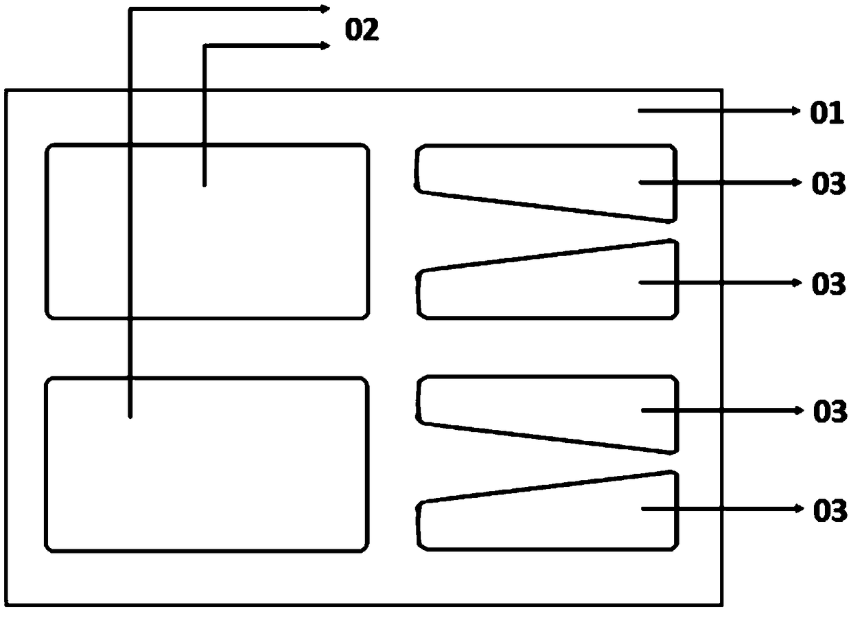
[0046]A casing for a soft-packed lithium-ion battery, comprising a main body, one side of the main body is provided with an outwardly protruding inner pit 02, or both sides of the main body are respectively provided with an outwardly protruding inner pit 02, and the two inner pits 02 Symmetrically arranged; one side of the main body is provided with an air bag that needs to be removed after exhaust packaging, and at least one small pit 03 protruding outward is provided on the air bag.

[0047] A plurality of small pits 03 are symmetrically arranged on both sides of the air bag, and the small pits 03 on different sides are arranged symmetrically with respect to the air bag. The cross-sectional shape of the small pit 03 parallel to the air bag is trapezoidal. The shorter one of the parallel sides is close to the main body, the right-angled side of the two non-parallel sides is close to the top or bottom of the cell, and the corners of the small pit 03 are rounded.

[0048] A cas...

Embodiment 2

[0067] Before step S0, the fabrication of bare cells is also included. The positive electrode sheet and the negative electrode sheet are prepared according to the current commercialized conventional process, and then prepared into bare cells together with the separator. The thickness of the bare cell is less than 2.2mm.

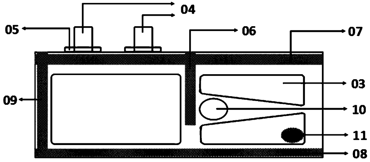
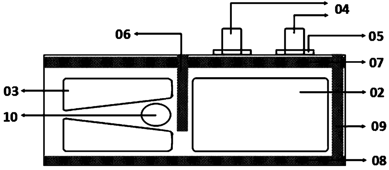
[0068] S0: Production of the battery casing: According to the thickness of the bare cell, the shell punching method of the aluminum-plastic film is a single pit, that is, only one inner pit 02 is punched. There are four right-angled trapezoidal small pits 03 on the upper punch of the air bag.

[0069] S1: Top sealing and side sealing: Put the bare cell into the inner pit 02, perform top sealing and side sealing according to certain packaging parameters, and the inner sealing area of ​​the top sealing is 0.8mm.

[0070] S2: Corner pre-encapsulation: In order to prevent the corners connecting the air bag and the bottom of the main body from being damaged due t...


PUM

PropertyMeasurementUnit
Thicknessaaaaaaaaaa
Thicknessaaaaaaaaaa

Abstract

The invention discloses a pouch lithium ionic battery case. The case comprises a main body, wherein an air bag is arranged on one side of the main body, and should be cut off after exhausted package;at least one pit is formed in the air bag and is raised outward; a case coated naked cell is subjected to top sealing and side sealing through the pit in the air bag, the volume of gas which is generated in air bag accommodation and formation can be improved; the section of the pit, parallel to the air bag, has a trapezoid shape, the shorter side of the two parallel sides of the trapezoid is closeto the main body, the outlet from which gas and electrolyte are exhausted is turned from narrow to wide, the electrolyte discharge speed can be effectively reduced, and the risk of polluting the battery case and lead by electrolyte flowing out from the air bag can be effectively reduced; and furthermore, a suction nozzle of an automatic injection machine can be placed among pits on the same sideof the air bag, so that the air bag area can be effectively utilized, and the case material can be saved. The pouch lithium ionic battery case is applied to the technical field of batteries.

Description

technical field [0001] The invention relates to the technical field of batteries, in particular to a casing of a soft-pack lithium-ion battery and a packaging method thereof. Background technique [0002] With the rapid development of today's science and technology, electronic information products occupy an increasingly important position in people's daily life. Lithium-ion batteries have become indispensable chemical power sources due to their high energy density, long cycle life, and high operating voltage. Compared with lithium-ion batteries with steel shells and aluminum shells, soft-pack lithium-ion batteries have grown rapidly due to their advantages such as light weight, good safety performance, unlimited shape, and simple protection design. [0003] At present, when the soft-pack lithium-ion battery is exhausted and packaged after formation, most of the air bags are placed flat, and then the air bag is pierced, pumped, and finally packaged. This method is likely to...

Claims


Application Information

Patent Timeline
IPC IPC(8): H01M2/02H01M10/058H01M10/0525H01M2/36H01M2/12H01M50/116H01M50/317H01M50/609
CPCH01M10/0525H01M10/058H01M50/116H01M50/317H01M50/60Y02E60/10Y02P70/50
Inventor 林珍艳易四勇李景夫林洋
Owner 桑顿新能源科技(长沙)有限公司
Why Eureka
Try Eureka