Semi-automatic laminator and laminating method

A film laminating machine, semi-automatic technology, applied in the direction of battery assembly, sustainable manufacturing/processing, climate sustainability, etc., can solve the problems of many bubbles, cannot meet the needs of mass production of lithium batteries, low efficiency, etc., and achieve film consistency Good, high film sticking efficiency, simple operation

Pending Publication Date: 2019-02-22
BEIJING PRIDE NEW ENERGY BATTERY
View PDF0 Cites 2 Cited by
  • Summary
  • Abstract
  • Description
  • Claims
  • Application Information

AI Technical Summary

Problems solved by technology

[0002] At present, the traditional film attachment method of lithium-ion batteries is that the film needs to be manually cut and then pasted on the surface of the battery. There are many air bubbles and low efficiency, which cannot meet the mass production needs of lithium batteries.

Method used


Image

  • Semi-automatic laminator and laminating method
  • Semi-automatic laminator and laminating method
  • Semi-automatic laminator and laminating method

Examples


Embodiment 1

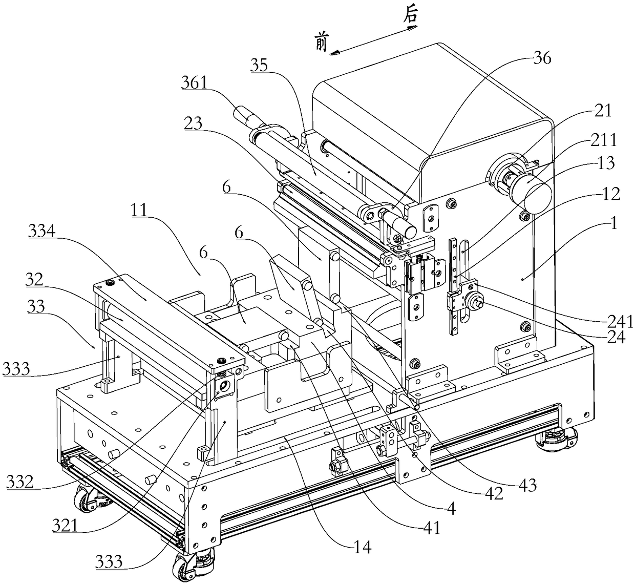
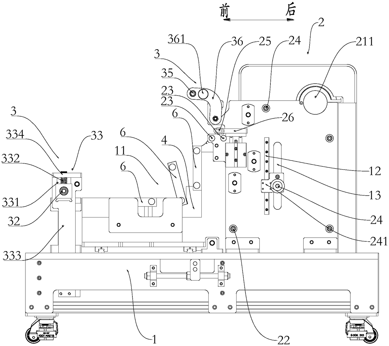
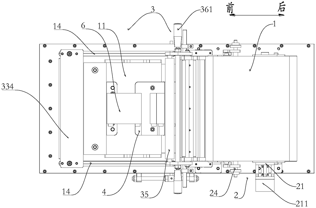
[0044] Such as Figure 1-Figure 4 As shown, a semi-automatic film laminating machine of this embodiment includes a frame 1, a film feeding device 2 and a film pressing device 3, and the film feeding device 2 and the film pressing device 3 can be detachably mounted on the frame 1 , the frame 1 between the laminating device 3 and the film feeding device 2 is reserved a coating area 11 for installing the tooling fixture 4, and the film feeding device 2 transports the packaging film 5 forward to the Above the coating area 11 and through the film pressing device 3, the packaging film is pressed and fixed on the outer side wall of the article to be packaged in the jig 4.

[0045] Wherein, the item to be packaged in this embodiment is a cubic structure of any size, such as a new energy battery, a packaging box, a tool box, and the like. In this embodiment, when describing the structure and principle of the semi-automatic film laminating machine, the battery 6 used in the battery pac...

Embodiment 2

[0067] Such as Figure 4 As shown, a method of using the above-mentioned semi-automatic film sticking machine in this embodiment to carry out film sticking comprises the following steps:

[0068] S1, install the tooling fixture in the coating area, and place the items to be packaged in the chute of the tooling fixture obliquely;

[0069] S2, open the film feeding device, the film feeding device sends the packaging film to the film outlet, then manually pull the packaging film, attach the end of the packaging film to the first edge of the upper end of the article to be packaged, and smooth it;

[0070] S3, then put the item to be packaged on the intermediate platform of the tooling fixture, manually pull the packaging film forward and downward, so that the item to be packaged lies flat on the intermediate platform, and the packaging film above the item to be packaged is inclined at Above the items to be packaged; (At this time, in order to avoid the backflow of the packaging f...


PUM


Abstract

The invention relates to a semi-automatic laminator and a laminating method. The semi-automatic laminator comprises a rack, a film feeding device and a film pressing device, wherein the film feeding device and the film pressing device are detachably arranged on the rack; a coating area used for mounting jigs and fixtures is reserved on the rack between the film pressing device and the film feedingdevice; and according to the film feeding device, packaging films are forwards transported to the upper side of the coating area and fixedly pressed on outer side walls of articles positioned in thejigs and fixtures by virtue of the film pressing device. According to the semi-automatic laminator disclosed by the invention, laminating and packaging of to-be-packaged articles can be rapidly and accurately completed, and due to the arrangement of the coating area, the jigs and fixtures of various models can be rapidly replaced. For example, if the to-be-packaged articles are batteries, the jigsand fixtures for batteries of various models can be rapidly replaced in the coating area.

Description

technical field [0001] The invention relates to the fields of new energy batteries and new energy vehicles, in particular to a semi-automatic film sticking machine and a film sticking method. Background technique [0002] At present, the traditional film attachment method of lithium-ion batteries is that the film needs to be manually cut and then pasted on the surface of the battery. There are many air bubbles and low efficiency, which cannot meet the mass production needs of lithium batteries. Contents of the invention [0003] The technical problem to be solved by the present invention is to provide a semi-automatic film laminating machine and film laminating method for the deficiencies of the prior art. [0004] The technical solution of the present invention to solve the above-mentioned technical problems is as follows: a semi-automatic film laminating machine, including a frame, a film feeding device and a film pressing device, the film feeding device and the film pre...

Claims


Application Information

Patent Timeline
Patent Type & Authority Applications(China)
IPC IPC(8): H01M10/04
CPCH01M10/0404Y02P70/50
Inventor 贾志佳于光赵锋邓翔杨三虎
Owner BEIJING PRIDE NEW ENERGY BATTERY
Why Eureka
Try Eureka