
Anti-interference antenna and manufacturing method thereof

A manufacturing method and antenna technology, applied to antennas, antenna coupling, antenna arrays, etc., can solve problems such as high requirements for operators, reduced antenna anti-interference performance, and increased antenna manufacturing costs

Pending Publication Date: 2019-02-22
SHENZHEN MERRYTEK TECHNOLOGY CO LTD
View PDF0 Cites 6 Cited by
  • Summary
  • Abstract
  • Description
  • Claims
  • Application Information

AI Technical Summary

Problems solved by technology

However, since the feeding point of the radiation source is relatively close to the central point, and the central point is relatively small, in the process of connecting with welding materials, on the one hand, it is easy to cause the feeding point of the radiation source to The electrical point and the center point are directly connected. On the other hand, it will also cause poor contact between the center point of the radiation source and the reference ground, which will affect the stability of the electromagnetic wave radiated from the antenna, which is serious. may cause the antenna to fail to work normally
Moreover, in the existing process of manufacturing the antenna, since the central point of the radiation source is relatively small, it takes a lot of man-hours to connect the central point of the radiation source with the preset position of the reference ground. Corresponding to the location of the equipment, not only prolongs the production cycle, but also has higher requirements for operators
In addition, once a deviation occurs so that the radiation source is fixedly maintained on one side of the reference ground, the central point of the radiation source is not electrically connected to the reference ground, that is, the radiation source is not Grounding will cause the anti-interference performance of the antenna to decrease, making the finished product yield of the antenna lower, and rework, disassembly and maintenance will increase the manufacturing cost of the antenna

Method used


Image

  • Anti-interference antenna and manufacturing method thereof
  • Anti-interference antenna and manufacturing method thereof
  • Anti-interference antenna and manufacturing method thereof

Examples


Embodiment Construction

[0111] The following description serves to disclose the present invention to enable those skilled in the art to carry out the present invention. The preferred embodiments described below are only examples, and those skilled in the art can devise other obvious variations. The basic principles of the present invention defined in the following description can be applied to other embodiments, variations, improvements, equivalents and other technical solutions without departing from the spirit and scope of the present invention.

[0112] Those skilled in the art should understand that in the disclosure of the present invention, the terms "vertical", "transverse", "upper", "lower", "front", "rear", "left", "right", " The orientation or positional relationship indicated by "vertical", "horizontal", "top", "bottom", "inner", "outer", etc. is based on the orientation or positional relationship shown in the drawings, which are only for the convenience of describing the present invention...


PUM


Abstract

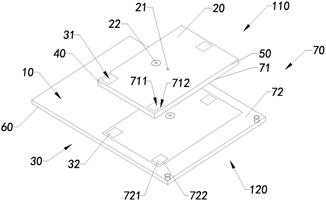
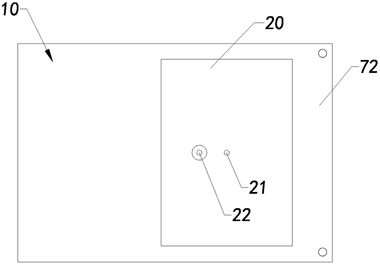
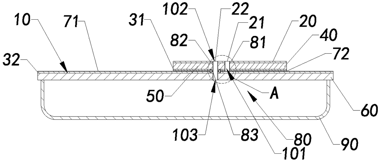
The invention discloses an anti-interference antenna and a manufacturing method thereof. The anti-interference antenna includes a reference site, a radiation source and a connection part. The radiation source is arranged adjacent to the reference site in a manner that a radiation gap is formed between the radiation source and the reference site. The radiation source is provided with a feed point and at least one ground point. The connection part includes a first connecting piece and a second connecting piece. The first connecting piece is electrically connected to the ground points of the radiation source. The second connecting piece is grounded. The second connecting piece forms the reference site. At least a part of the first connecting piece is electrically connected to at least a partof the second connecting piece.

Description

technical field [0001] The invention relates to an antenna, in particular to an anti-jamming antenna and its manufacturing method. Background technique [0002] Antennas can transmit signals or transmit energy by transmitting and / or receiving electromagnetic waves, and are widely used in radio communication, radar, navigation, television, broadcasting, etc. For example, the common microwave detector in recent years is to use an antenna to emit microwaves of a predetermined frequency to detect the motion state of objects in the target area in a target area, and the electromagnetic wave radiated by the antenna is used as the carrier of the signal Conducting information is the key to complete microwave detection. [0003] However, it is well known that when the frequency bands of two or more electromagnetic waves are close to each other, mutual interference between the electromagnetic waves is likely to occur, and the closer the frequencies of the electromagnetic waves are, th...

Claims


Application Information

Patent Timeline
IPC IPC(8): H01Q1/38H01Q1/48H01Q1/50H01Q1/52H01Q21/00
CPCH01Q1/38H01Q1/48H01Q1/50H01Q1/52H01Q21/00
Inventor 邹高迪邹新
Owner SHENZHEN MERRYTEK TECHNOLOGY CO LTD
Learn More