Rotor core, outer rotor motor, driving motor for electric vehicle and manufacturing method

A manufacturing method and rotor core technology, applied in electric vehicles, motors, electric components, etc., can solve the problems of increased material cost, low utilization rate of rotor core materials, waste of raw materials, etc., to ensure the integrity of the magnetic circuit, improve the Material utilization and the effect of ensuring structural strength

Active Publication Date: 2019-02-22
奇瑞新能源汽车股份有限公司
View PDF5 Cites 6 Cited by
  • Summary
  • Abstract
  • Description
  • Claims
  • Application Information

AI Technical Summary

Problems solved by technology

[0003] However, in order to reduce the cost of the product and save materials, the block-type stator core began to be used in large quantities. The block-type stator core is mostly punched separately, and no remaining inner ring material is used for rotor punching. The integral rotor punching is performed separately. The blanking will lead to low material utilization and waste of raw materials
[0004] Especially in the field of permanent magnet drive motors for electric vehicles, with the increasing demand for high-power motors, the outer diameter of the motor and the outer diameter of the rotor core also increase, and the aperture of the output shaft is larger, resulting in integral The material utilization of the rotor core is further reduced
In the field of external rotor motors, due to its structural characteristics, the rotor is located on the outer ring of the stator, and the material utilization rate of the integral rotor core is also low
[0005] In addition, in the production process of the motor, the scrap rate of the rotor core is generally higher than that of the stator core, but for matching, the production of the rotor core is also required separately, which further reduces the utilization rate of materials and leads to an increase in material costs

Method used


Image

  • Rotor core, outer rotor motor, driving motor for electric vehicle and manufacturing method
  • Rotor core, outer rotor motor, driving motor for electric vehicle and manufacturing method
  • Rotor core, outer rotor motor, driving motor for electric vehicle and manufacturing method

Examples


Embodiment Construction

[0026] The specific embodiment of the present invention will be described in further detail by describing the embodiments below with reference to the accompanying drawings, the purpose is to help those skilled in the art to have a more complete, accurate and in-depth understanding of the concept and technical solutions of the present invention, and contribute to its implementation.

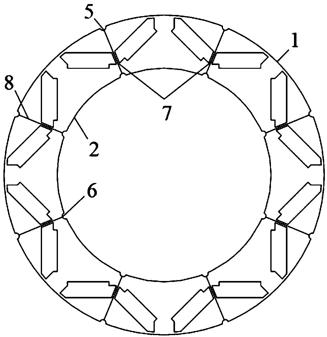
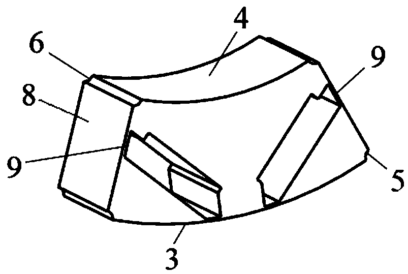
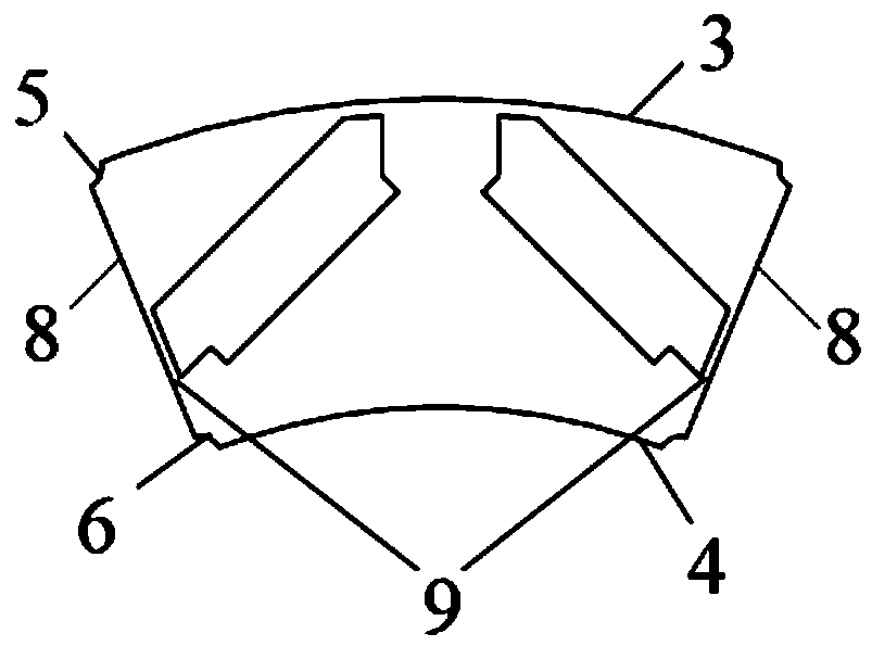
[0027] Such as figure 1 and figure 2 As shown, the present invention provides a rotor core, which is a ring-shaped structure spliced ​​by a plurality of arc-shaped core units. Located at the center of the magnetic isolation bridge.

[0028] Specifically, as figure 1 and figure 2 As shown, the radian of the core unit is 45 degrees, and the core unit is an arc-shaped block structure. There are eight core units in total, and the eight core units are arranged in a circle. connected to form a complete ring-shaped rotor core. Each core unit has two splicing surfaces. The two splicing surfaces of...


PUM


Abstract

The invention discloses a rotor core, which is an annular structure formed by splicing a plurality of arc-shaped core units. Each core unit has splicing surfaces which are attached to adjacent core units, and the splicing surfaces are located at the centers of magnetic insulation magnetic bridges. The rotor core of the invention adopts a splicing block structure, which can improve the material utilization rate and reduce the material cost; at the same time, splicing joints are disposed at the centers of the magnetic insulation magnetic bridges of permanent magnets and the welding slots are arranged at both ends of the splicing joints. After splicing, the magnetic circuit integrity of the rotor core is ensured, the structural strength is ensured, and the magnetic permeability and mechanicalproperties of the rotor core are not affected. The invention also discloses an outer rotor motor, a driving motor for an electric vehicle and a method for manufacturing the rotor core.

Description

technical field [0001] The invention belongs to the technical field of motors, in particular, the invention relates to a rotor core, an outer rotor motor, a driving motor for an electric vehicle and a method for manufacturing the rotor core. Background technique [0002] Most of the rotor cores of existing motors are formed by lamination and riveting of integral circular rotor punches. The rotor punches are mainly punched with the remaining material in the inner ring of the stator punches. Carry out matching punching. [0003] However, in order to reduce the cost of the product and save materials, the block-type stator core began to be used in large quantities. The block-type stator core is mostly punched separately, and no remaining inner ring material is used for rotor punching. The integral rotor punching is performed separately. Excessive blanking will lead to low material utilization and waste raw materials. [0004] Especially in the field of permanent magnet drive m...

Claims


Application Information

Patent Timeline
Patent Type & Authority Applications(China)
IPC IPC(8): H02K1/27H02K1/28H02K15/03
CPCH02K1/2786H02K1/28H02K15/03Y02T10/64
Inventor 姚学松陈士刚刘靓沙文瀚杭孟荀张杰王瑛舒晖陶文勇夏荣鑫李庆国
Owner 奇瑞新能源汽车股份有限公司
Why Eureka
Try Eureka