

Rotor punching piece manufacturing process
A technology of rotor punching and manufacturing process, which is applied in the field of rotor punching manufacturing technology, can solve problems such as high vibration intensity, distance deviation, and poor processing accuracy, and achieve the effects of increasing magnetic permeability, reducing vibration intensity, and improving processing accuracy
Active Publication Date: 2019-02-22
温岭市钢锋冲件有限公司
View PDF10 Cites 9 Cited by
- Summary
- Abstract
- Description
- Claims
- Application Information
AI Technical Summary
Problems solved by technology
[0004] In the punching stamping process described above, the stator punching rough blank is first cut and punched, and then the driving keyway and the punching process hole are cut and punched on the rough blank, and then the rotor punch is cut from the center of the stator punch. Finally, the rotor middle slot (called the shaft hole in the present invention) that is used to pass through the rotating shaft of the rotor on the rotor punching sheet is processed again. Small, so it is easy to produce an offset during the blanking process, so that there is a deviation in the distance between each part of the outer circular contour of the rotor punching sheet and the middle slot of the rotor, and the motor rotor is in the process of rotation, so it is passed through the rotor The rotating shaft in the punching center is the center of rotation, so the distance from the outer circle of the rotor punching to the center of the shaft hole will directly affect the eccentric force of the rotor when it rotates. Poor machining accuracy will lead to excessive vibration during motor startup.
Method used
View moreImage
Smart ImageViewing Examples

Examples
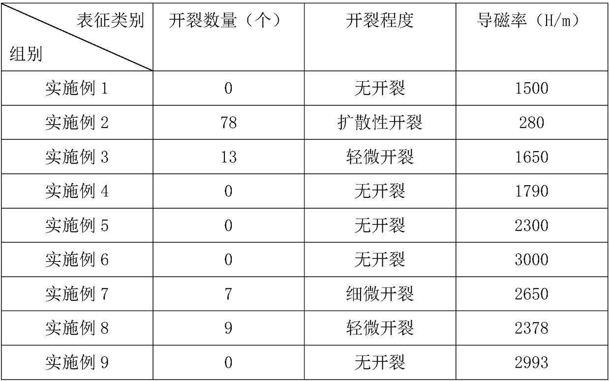
Embodiment 1
[0052] Example 1: The stamped sheet is not subjected to any heat treatment.
Embodiment 2
[0053] Embodiment 2: The punched piece is directly immersed in tap water for one-time cooling and quenching.
Embodiment 3
[0054] Embodiment 3: Punching is divided into two stages of initial cooling and final cooling for cooling and quenching, and the initial cooling stage is 5L / min·m 2 The spraying speed is sprayed on the punching sheet, and after the punching sheet is cooled to 600-700 degrees Celsius, switch to 8L / min·m 2 Spray the punched sheet at the final cooling spray speed until the punched sheet cools to room temperature.
Login to View More PUM
 Abstract
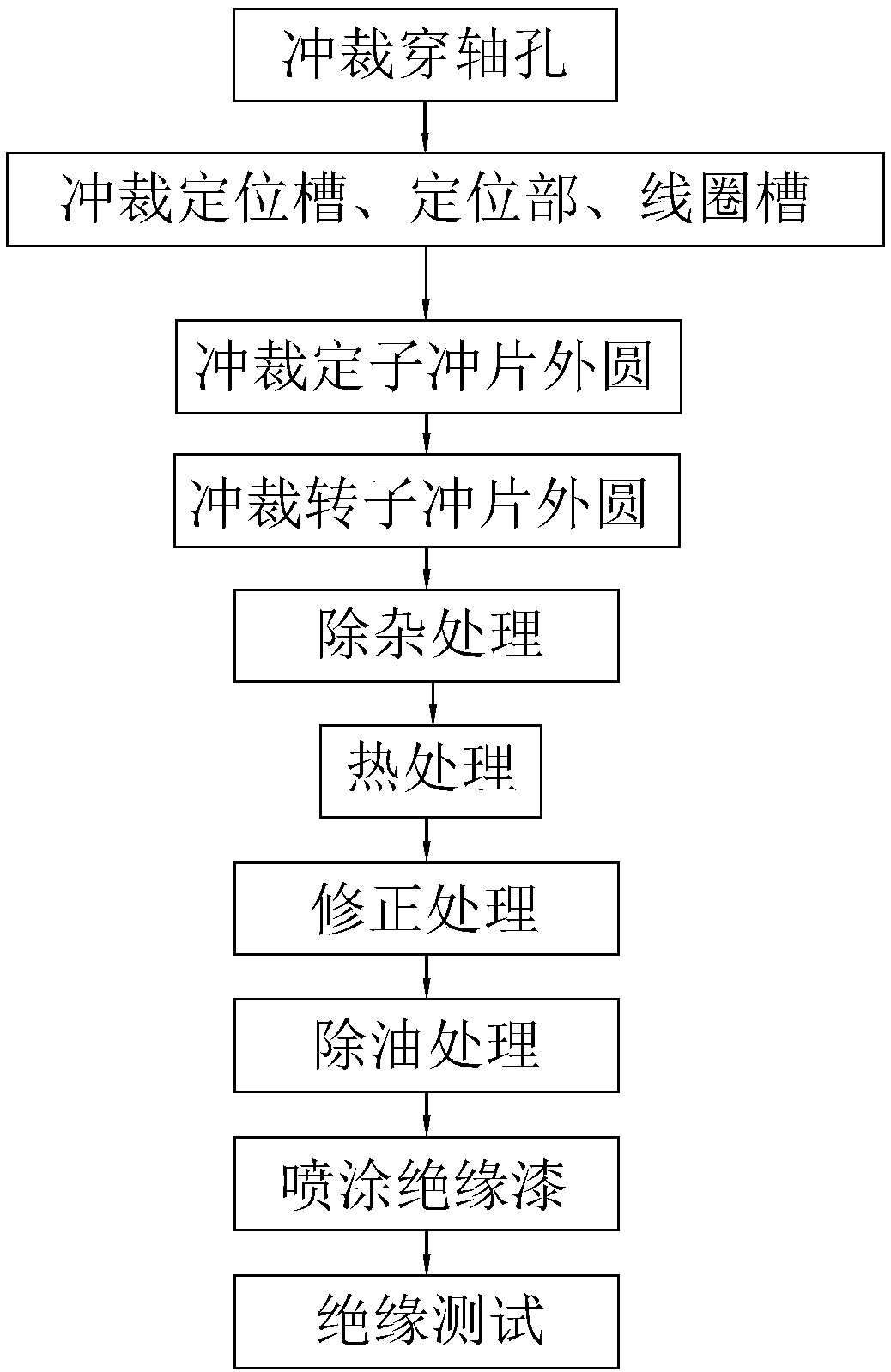
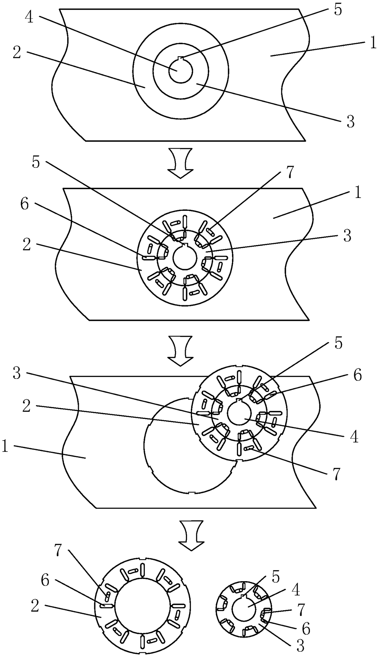
The invention discloses a rotor punching piece manufacturing process and relates to a punching process. The process roughly comprises: firstly, punching a shaft hole on a plate-shaped silicon steel sheet; then, punching a coil groove with the shaft hole as a reference; punching a stator punching piece outer circumference with the shaft hole as a reference; cutting off a rotor punch piece from thestator punch piece with the shaft hole as a reference; and subjecting the stator and rotor punching pieces to correction, insulation varnish painting, and insulation detection, and assembling the rotor punching piece if qualified. The method has the following advantages and effects that the processing method of punching the shaft hole first and then punching with the shaft hole as a reference canreduce the offset of the punching piece during the processing, improves the machining accuracy of the stator and rotor punching pieces, reduces the eccentric inertia of the rotor at the start of the motor, thereby achieving a purpose of reducing the vibration strength during the start process of the motor.
Description
technical field [0001] The invention relates to a blanking process, in particular to a rotor punching manufacturing process. Background technique [0002] Motor stator punching and rotor punching are important parts in the motor. They are used to cooperate with copper core coils to convert electrical energy into mechanical energy, thereby achieving the effect of output torque. Therefore, the precision of stator punching and rotor punching in manufacturing And the quality will directly affect the performance of the motor after assembly. [0003] At present, the Chinese invention patent with the application publication number of CN101860134A discloses a stamping process for the stator and rotor of a wind power generator. It first punches the rotor light sheet on the sheet material, and at the same time punches the outer circle profile of the stator on the rotor light sheet, The process drives the keyway and the punching process hole; then, based on the punching process hole, ...
Claims
Login to View More Application Information
Patent Timeline
 Patent Type & AuthorityApplications(China)
IPC IPC(8): H02K15/02
CPCH02K15/026
Inventor李殷芝
Owner温岭市钢锋冲件有限公司