Hydraulic clamping fixture for intelligent displayer accessory machining

A hydraulic clamping and display technology, which is applied in the direction of manufacturing tools, metal processing equipment, metal processing machinery parts, etc., can solve the problems of unstable workpiece positioning, high labor intensity, and too tight pressing, so as to improve production efficiency and reduce Artificial use, the effect of preventing sliding

Inactive Publication Date: 2019-02-26
KUNSHAN KERSEN SCI & TECH
View PDF6 Cites 1 Cited by
  • Summary
  • Abstract
  • Description
  • Claims
  • Application Information

AI Technical Summary

Problems solved by technology

[0003] Traditional CNC fixtures use simple fixtures and positioning pins for positioning operations, and rely on workers to load and unload and pos

Method used


Image

  • Hydraulic clamping fixture for intelligent displayer accessory machining
  • Hydraulic clamping fixture for intelligent displayer accessory machining
  • Hydraulic clamping fixture for intelligent displayer accessory machining

Examples


Embodiment 1

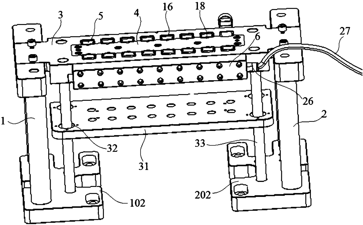
[0022] Embodiment 1: A hydraulic clamping fixture for processing intelligent display accessories, including a left support 1, a right support 2, a fixed plate 3, a positioning plate 4, a chuck 5 and a pressure mechanism 6, the two fixed plates 3 The ends are fixedly connected with the left support 1 and the right support 2 respectively, the positioning plate 4 is fixedly connected with the fixed plate 3, the pressure mechanism 6 is respectively symmetrically installed on the surface of both sides of the fixed plate 3, and the chucks 5 are respectively installed At the end of the piston rod 7 of the pressure mechanism 6;

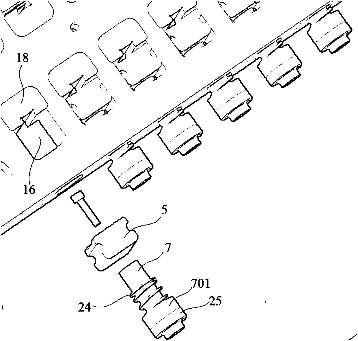
[0023] Both sides of the upper surface of the fixing plate 3 are symmetrically opened with a number of uniformly arranged relief through holes 16, and the positioning protrusions 18 and chucks 5 of the positioning plate 4 are located in the relief through holes 16, wherein the positioning protrusions 18 Located on the side close to the center, the chuck 5 is ...

Embodiment 2

[0027] Embodiment 2: A hydraulic clamping jig for processing intelligent display accessories, including a left support 1, a right support 2, a fixed plate 3, a positioning plate 4, a chuck 5 and a pressure mechanism 6, the two fixed plates 3 The ends are fixedly connected with the left support 1 and the right support 2 respectively, the positioning plate 4 is fixedly connected with the fixed plate 3, the pressure mechanism 6 is respectively symmetrically installed on the surface of both sides of the fixed plate 3, and the chucks 5 are respectively installed At the end of the piston rod 7 of the pressure mechanism 6;

[0028] Both sides of the upper surface of the fixing plate 3 are symmetrically opened with a number of uniformly arranged relief through holes 16, and the positioning protrusions 18 and chucks 5 of the positioning plate 4 are located in the relief through holes 16, wherein the positioning protrusions 18 Located on the side close to the center, the chuck 5 is loca...


PUM


Abstract

The invention discloses a hydraulic clamping fixture for intelligent displayer accessory machining. The hydraulic clamping fixture comprises a left support, a right support, a fixed plate, a positioning plate, clamping heads and pressure mechanisms; the two ends of the fixed plate are fixedly connected with the left support and the right support respectively, the positioning plate is fixedly connected with the fixed plate, the clamping heads are located on the side away from the center, T-shaped blind holes corresponding to stepped holes are uniformly formed in the inner side surfaces of the pressure mechanisms, each hydraulic oil hole is connected with an oil pump through a hydraulic oil tube, the lower ends of guide pillars are connected with a left substrate of the left support and a right substrate of the right support respectively, two guide pillars located on the same side in the four guide pillars are anti-skid guide columns, a trapezoidal section is arranged on the side, closeto the exterior, of each anti-skid guide column, an included angle exists between each trapezoidal section and a vertical face, and the upper bottom of the trapezoidal section is shorter than the lower bottom. Accordingly, by means of knurling, the frictional force of the anti-skid guide columns is increased, the phenomenon that a movable plate slides downwards is effectively prevented, the stability of a to-be-machined material in the machining process is guaranteed, and the machining precision is guaranteed.

Description

technical field [0001] The invention relates to a hydraulic clamping jig for processing intelligent display accessories, and relates to the field of high precision machining. Background technique [0002] Smartphones are the most widely used entertainment and communication devices, and their update speed is relatively fast. Therefore, smartphone manufacturers have also put forward higher requirements. Smartphone components are inseparable from machine tool equipment, and machine tool fixtures are one of the important technological equipment to ensure machine tool processing quality, improve production efficiency, and reduce labor intensity. However, there are many problems in how to stably and effectively position the workpiece during processing. . [0003] The traditional CNC fixtures mostly use simple fixtures and positioning pins for positioning operations, and are loaded and unloaded by workers for positioning. This will lead to unstable positioning of the workpiece, to...

Claims


Application Information

Patent Timeline
IPC IPC(8): B23Q3/08
CPCB23Q3/062B23Q3/082B23Q3/06B23Q3/08
Inventor 陶勋辉崔水利
Owner KUNSHAN KERSEN SCI & TECH
Why Eureka
Try Eureka