
Pump gate and control system

A control system and controller technology, applied in water conservancy projects, sea area projects, coastline protection, etc., to achieve the effects of small footprint, high hydraulic efficiency, and enhanced drainage

Pending Publication Date: 2019-02-26
JIANGSU UNIV +1
View PDF9 Cites 0 Cited by
  • Summary
  • Abstract
  • Description
  • Claims
  • Application Information

AI Technical Summary

Problems solved by technology

However, most of the current pump gates realize one-way drainage. How to realize two-way water distribution and make more use of the technical advantages of the integrated pump gate is a problem that needs to be solved.

Method used


Image

  • Pump gate and control system
  • Pump gate and control system
  • Pump gate and control system

Examples


Embodiment approach

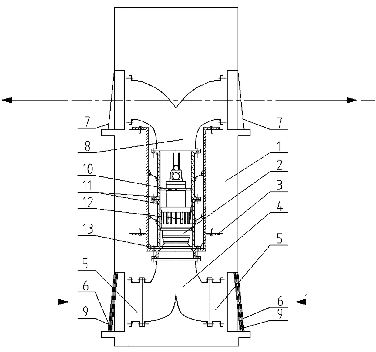
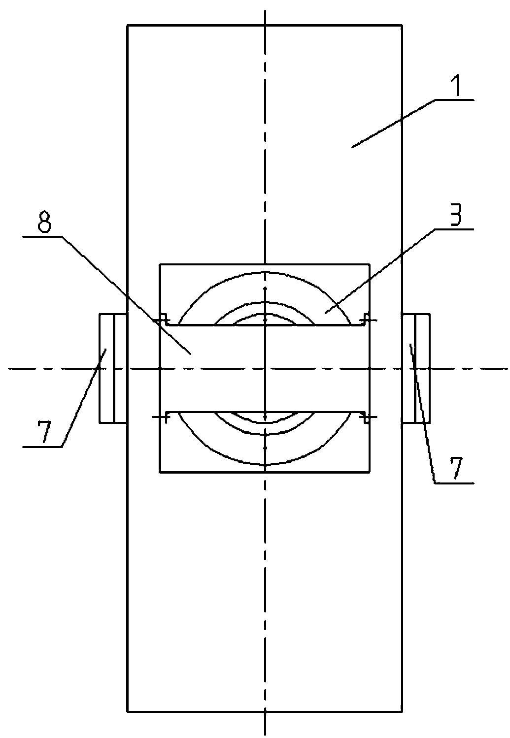
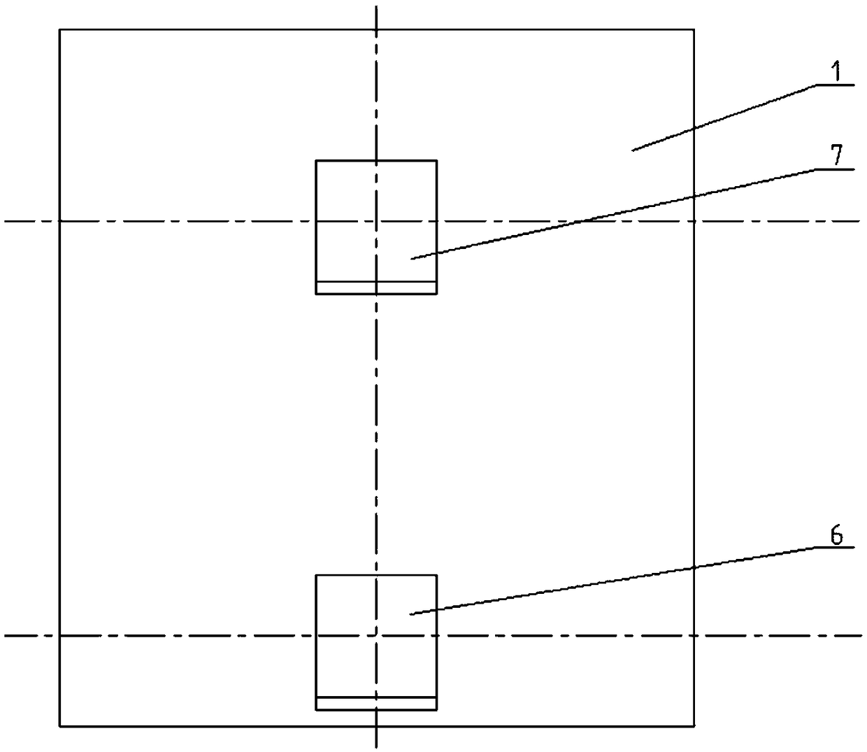
[0055] figure 1 , 2 Shown in and 3 is an embodiment of the pump gate of the present invention. The pump gate includes a gate plate 1, a sleeve 3, a pump barrel 11, a vertical axial flow pump 2, a bidirectional inlet flow channel 4, and an outlet bidirectional Runner 8;

[0056] The sleeve 3 is installed in the gate 1;

[0057] The pump barrel 11 is installed in the sleeve 3;

[0058] The vertical axial flow pump 2 is installed in the pump cylinder 11;

[0059] The two-way inlet channel 4 is located below the inside of the gate 1, one end of the two-way inlet channel 4 is connected to the water inlet of the vertical axial flow pump 2, and the other end is respectively connected to the water inlets on both sides of the gate 1, the gate The water inlets on both sides of the plate 1 are respectively equipped with imported two-way valves 6;

[0060] The outlet two-way flow channel 8 is located above the inside of the gate 1, and one end of the outlet two-way flow channel 8 is co...

Embodiment 2

[0080] A control system for a pump gate, comprising the pump gate described in Embodiment 1 and a controller;

[0081] The controller is respectively connected with the flashboard 1, the vertical axial flow pump 2, the inlet two-way flap door 6 and the outlet two-way flap door 7.

[0082] When the water enters from the left side and the water comes out from the right side: the controller controls the gate 1 to close, the left inlet two-way flap door 6 and the right outlet two-way flap door 7 open, the right inlet two-way flap door 6 and the left outlet two-way flap door 7 is in the closed state, and the vertical axial flow pump 2 is started to run in the forward direction. At this time, water enters from the left side and water exits from the right side.

[0083] When water enters from the right side and water exits from the left side: the controller controls the gate 1 to close, the right inlet bidirectional flap door 6 and the left outlet bidirectional flap door 7 open, the ...


PUM


Abstract

The invention provides a pump gate and a control system. The pump gate comprises a gate plate, a sleeve, a pump cylinder, a vertical axial flow pump, a two-way inlet flow passage, an outlet two-way flow passage and a controller; the sleeve is installed in the gate plate; the pump cylinder is installed in the sleeve; the vertical axial flow pump is installed in the pump cylinder; one end of the two-way inlet flow passage is connected with a water inlet of the vertical axial flow pump, the other end of the two-way inlet flow passage is connected with water inlets in the two sides of the gate plate separately, and the water inlets in the two sides of the gate plate are provided with inlet two-way flap valves respectively; one end of the outlet two-way flow passage is connected with a water outlet of the vertical axial flow pump, the other end of the outlet two-way flow passage is connected with water outlets in the two sides of the gate plate separately, and the water outlets in the two sides of the gate plate are provided with outlet two-way flap valves respectively. The controller is connected with the gate plate, the vertical axial flow pump, the inlet two-way flap valves and the outlet two-way flap valves separately. According to the pump gate and the control system, the function of two-way drainage in the integrated structure of the pump gate is achieved, few land resources are occupied, and the flood drainage and running water introduction functions of the integrated pump gate are strengthened.

Description

technical field [0001] The invention belongs to the field of water conservancy engineering research, and in particular relates to a pump gate and a control system. Background technique [0002] The gate station is an important facility for hydraulic flood control and drainage. The traditional gate station construction usually adopts the combination of axial flow pumps and sluice gates. Pump houses are built on both sides or one side of the gate to realize the power lifting or artesian drainage of the same water body. . The traditional gate station separation old-fashioned pump gate project requires large investment, long construction period, land acquisition and demolition, and covers a large area. For reservoirs and lakes that need to be drained and stored according to different seasons, traditional two-way pumping stations must adopt double-layer two-way flow channels. By arranging water pumps in different directions, the functions of water drainage and water distribution...

Claims


Application Information

Patent Timeline
Patent Type & Authority Applications(China)
IPC IPC(8): E02B7/36E02B7/20E02B8/02
CPCE02B7/20E02B7/36E02B8/023E02B8/026
Inventor 刘栋黄凯周旭唐正明许忠南
Owner JIANGSU UNIV
Learn More