Automatic barring device and control method

A technology of a turning device and a control method, which is applied in the direction of engine components, machines/engines, mechanical equipment, etc., can solve problems such as high labor intensity, hidden dangers of personal and equipment safety, and prone to danger and mistakes, so as to reduce labor intensity, The effect of improving personal and equipment safety, avoiding mistakes and dangers

Inactive Publication Date: 2019-02-26
QINGDAO JIENENG STEAM TURBINE GROUP CO LTD
View PDF9 Cites 1 Cited by
  • Summary
  • Abstract
  • Description
  • Claims
  • Application Information

AI Technical Summary

Problems solved by technology

However, manual operation is not only labor-intensive, time-consuming and labor-intensive, but also prone to danger and mistakes, which poses great safety hazards to people and equipment, and cannot meet the needs of modern production.
[0004] Therefore, how to provide an automa

Method used


Image

  • Automatic barring device and control method
  • Automatic barring device and control method

Examples


Embodiment Construction

[0034] In view of this, the core of the present invention is to provide an automatic cranking device, which can not only reduce labor intensity, save time and effort, but also avoid errors and dangers caused by on-site operations, thereby effectively improving personal and equipment safety.

[0035] Another core of the present invention is to provide an automatic cranking control method.

[0036] In order to enable those skilled in the art to better understand the solution of the present invention, the present invention will be further described in detail below in conjunction with the accompanying drawings and specific embodiments.

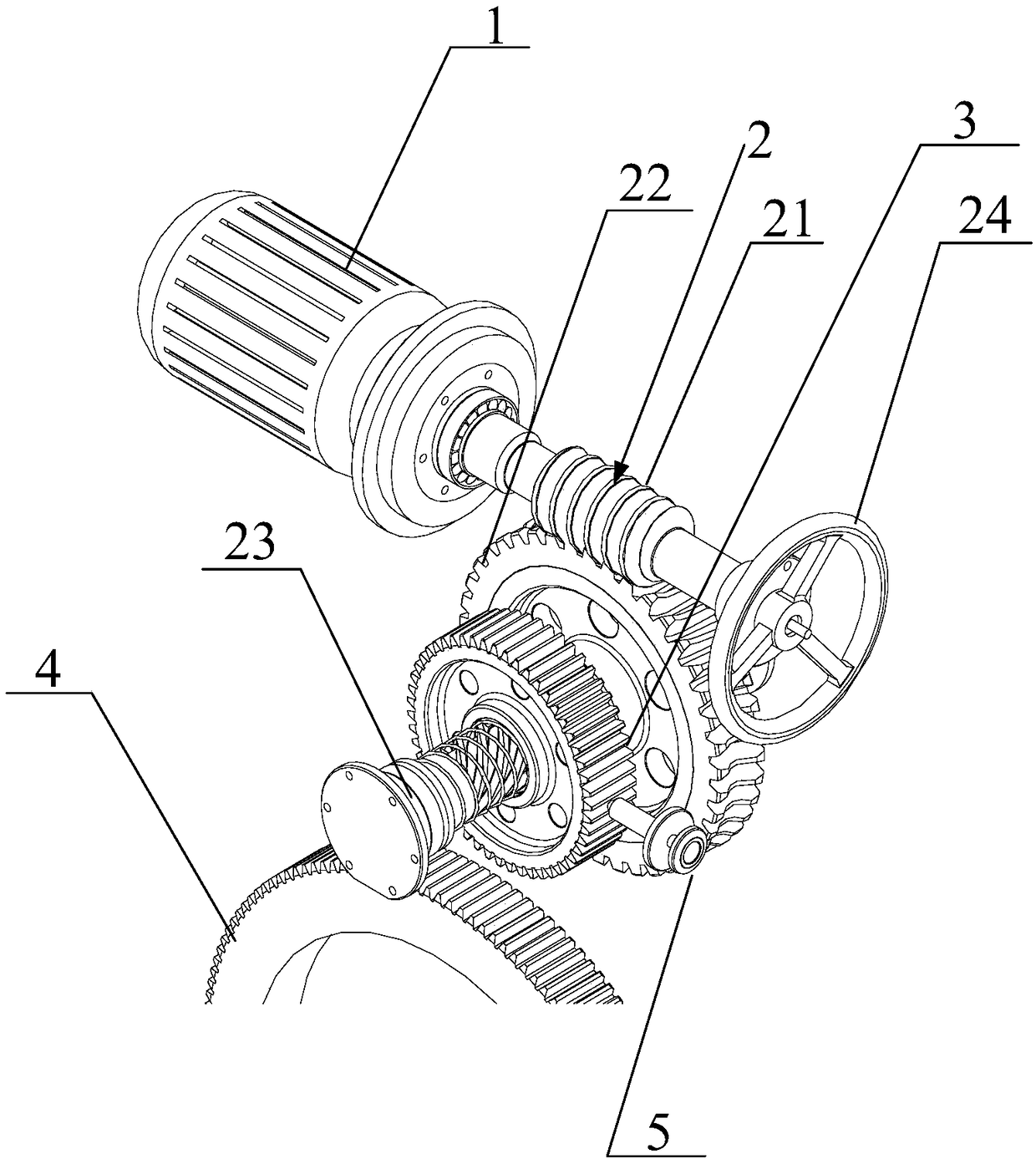
[0037] The automatic barring device disclosed in the embodiment of the present invention includes a barring drive motor 1, and a worm gear mechanism 2 for connecting with the barring drive motor 1. The worm gear mechanism 2 is sleeved with a lead screw, and There is a moving gear 3 for meshing with the turning gear 4, and the turning gear 4 is con...


PUM


Abstract

The invention discloses an automatic barring device. The barring device comprises a barring drive motor and a worm and gear mechanism used for being connected with the barring drive motor, wherein a lead screw sleeves the worm and gear mechanism and provided with a moving gear used for being meshed with a barring gear, and the barring gear is connected with a steam turbine. The barring device alsocomprises a barring input device used for abutting against the moving gear and a controller used for controlling the barring drive motor and the barring input device. According to the automatic barring device, by automatically controlling the barring drive motor and the barring input device, not only can the labor intensity be reduced, time and labor are saved, but also the errors and risks caused by field operation can be avoided, and the safety of personnel and equipment can be effectively improved. The invention also discloses an automatic barring control method.

Description

technical field [0001] The invention relates to the technical field of steam turbines, in particular to an automatic cranking device and a control method. Background technique [0002] The barring device is an important part of the steam turbine. The electric barring device is the most commonly used barring device. The electric motor drives the steam turbine to rotate at a low speed through a series of gear devices. Process: After the steam turbine is shut down, the high-temperature rotor is cooled evenly by the barring device to prevent the thermal bending of the rotor due to uneven cooling and heating. [0003] The barring input device is the main part of the electric barring device. In the traditional electric barring input device, the contact is generally pressed manually to push the contact against the moving gear set on the worm. When the moving gear cannot rotate Next, the lead screw on the worm moves to the turning gear and meshes with the turning gear, thereby real...

Claims


Application Information

Patent Timeline
IPC IPC(8): F01D25/36
CPCF01D25/36
Inventor 陈宝志宋鹏程姜世纲牛和山
Owner QINGDAO JIENENG STEAM TURBINE GROUP CO LTD
Why Eureka
Try Eureka