A frame strength test device based on a center pin loading mechanism

A technology of loading mechanism and strength test, applied in the direction of railway vehicle testing, etc., can solve the problems of asynchronization of the force state of the lateral stopper, unmonitoring of the balance of the force, and the large space occupied by the loading device, so as to avoid blocking interference, Easy assembly operation and maintenance, compact layout effect

Inactive Publication Date: 2019-02-26
CRRC CHANGCHUN RAILWAY VEHICLES CO LTD
View PDF3 Cites 8 Cited by
  • Summary
  • Abstract
  • Description
  • Claims
  • Application Information

AI Technical Summary

Problems solved by technology

[0006] In order to solve the problem that the X-axis lateral force loading device and the Y-axis longitudinal force loading device of the existing force-applying device for strength testing are designed separately and connected separately, the loading device occupies a large space and the manufacturing cost is high. ; The X-axis lateral force loading device with a large longitudinal span will cause the force state of the two lateral stoppers to be out of sync, and cause the problem of inaccurate mechanical load data; and there is no pressure transmission on the existing two traction rods. sense, therefore, the technical problem of whether the force balance of the two traction rod seats cannot be monitored, the invention provides a frame strength test device based on the center pin loading mechanism

Method used


Image

  • A frame strength test device based on a center pin loading mechanism
  • A frame strength test device based on a center pin loading mechanism
  • A frame strength test device based on a center pin loading mechanism

Examples


Embodiment Construction

[0043] The present invention will be described in further detail below in conjunction with the accompanying drawings.

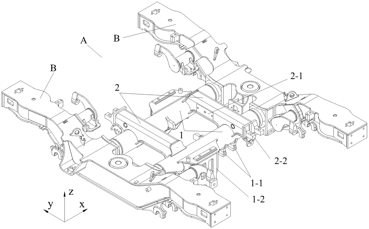
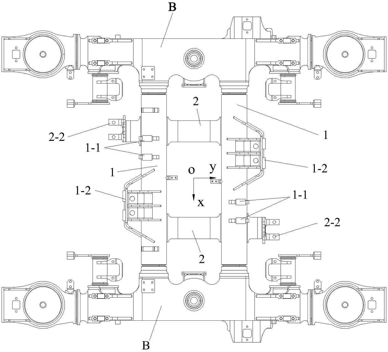
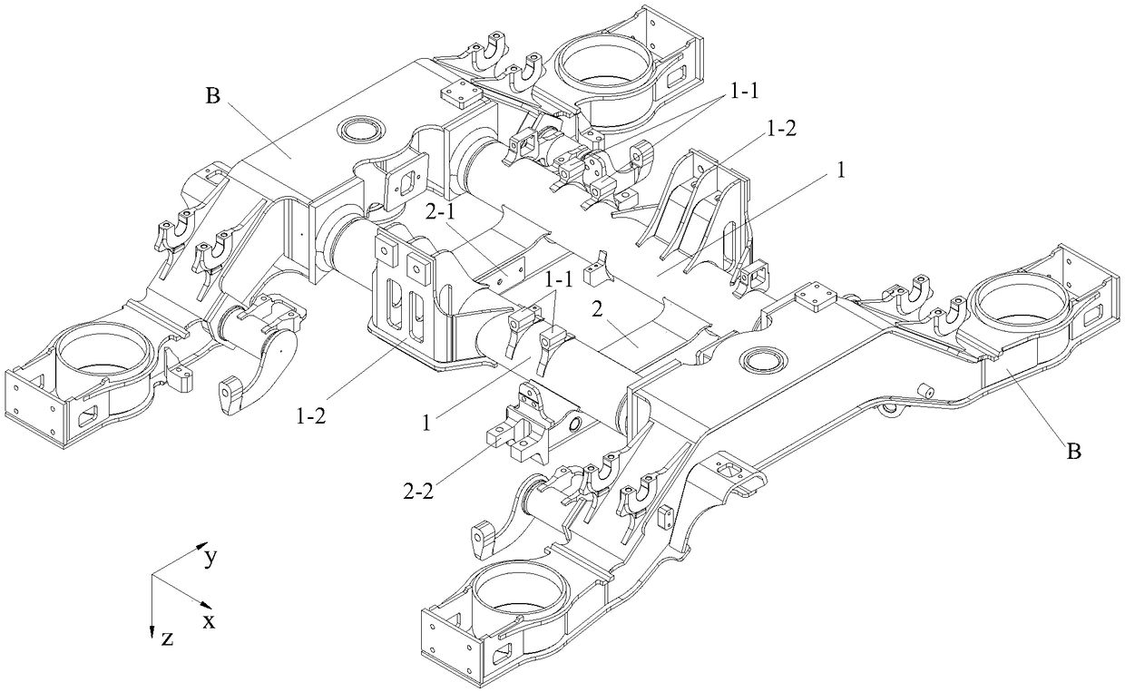
[0044] Such as Figure 4 to Figure 18 As shown, the frame strength test device based on the central pin loading mechanism of the present invention includes a simulated central pin loading mechanism, a universal spherical support 3, a lateral stop spherical support 8, two stop seat rubber pads 9, two measuring Force type traction rod 10, two lateral force loading actuating mechanisms 11 and longitudinal reaction rod 12, the simulated center pin loading mechanism includes tubular core barrel 4, force measuring traction rod seat 5, lateral force symmetrical slope loading seat 6 , the reaction rod loads the hinge shaft seat 7 and the lateral stopper spherical bearing 8; the lower end of the universal spherical bearing 3 is fixedly connected with the ground, the lower end of the core barrel 4 is fixedly connected with the universal spherical bearing 3, and its axi...


PUM


Abstract

The invention relates to a frame strength test device based on a center pin loading mechanism, belonging to the field of a force loading device for frame strength tests of railway vehicle bogies. Theframe strength test device based on a center pin loading mechanism comprises a simulation center pin loading mechanism, a universal spherical bearing, a transverse stop spherical bearing, two stop seat rubber pads, two force-measuring type traction rods, two transverse force loading actuators and a longitudinal counter-force rod, wherein the simulation center pin loading mechanism comprises a tubular core barrel, a force-measuring traction rod seat, a transverse force symmetrical slope surface loading seat, a counter-force rod loading hinge shaft seat and a transverse stop spherical bearing. The device has the advantages of exquisite structure, compact layout and easy assembly, operation and maintenance; the device can not only avoid the problems of component blocking interference and large time lag error of a load cell, but also greatly save the manufacturing cost, increase the test precision and improve the production efficiency.

Description

technical field [0001] The invention belongs to the field of force loading devices for railway vehicle bogie frame strength tests, and in particular relates to a frame strength test device based on a central pin loading mechanism. Background technique [0002] Since the bogie frame of a railway vehicle is the core component that bears the weight of the car body and transmits traction and braking power, after the theoretical design is completed, it is usually necessary to carry out a load strength test on the bogie frame of the initial production. When carrying out the load-bearing test on the key structure of the frame, it is usually necessary to apply force along the Z-axis vertical, X-axis transverse and Y-axis longitudinal directions of the frame at the same time, so as to continuously simulate the train's on-rail operating environment. Comprehensive force environment, so as to test the rationality of the mechanical structure of the bogie frame, by obtaining the dynamic f...

Claims


Application Information

Patent Timeline
Patent Type & Authority Applications(China)
IPC IPC(8): G01M17/08
CPCG01M17/08
Inventor 郭志瑞王宇史吏
Owner CRRC CHANGCHUN RAILWAY VEHICLES CO LTD
Why Eureka
Try Eureka