
Display panel and display device thereof

A display panel and substrate technology, applied in the direction of electric solid-state devices, semiconductor devices, organic semiconductor devices, etc., can solve the problems of color mixing and low light utilization rate, and achieve the effect of improving light utilization rate and reducing power consumption

Active Publication Date: 2019-02-26
WUHAN CHINA STAR OPTOELECTRONICS TECH CO LTD
View PDF6 Cites 7 Cited by
  • Summary
  • Abstract
  • Description
  • Claims
  • Application Information

AI Technical Summary

Problems solved by technology

[0007] One aspect of the present invention is to provide a display panel, which can effectively solve the problems of color mixing and low light utilization in the prior art

Method used


Image

  • Display panel and display device thereof
  • Display panel and display device thereof

Examples


Embodiment Construction

[0034] The technical solution of a display panel and a display device thereof involved in the present invention will be further described in detail with reference to the drawings and embodiments.

[0035] see figure 1 As shown, one embodiment of the present invention provides a display panel, including a blue light backlight module 20 , a polarizer 22 , a substrate 10 , an OC layer 12 , a color filter layer and a glass layer 24 arranged in sequence.

[0036] Wherein the color filter layer includes a first color resistance 14, a second color resistance 16, and a third color resistance 18 arranged at intervals. Quantum dots corresponding to their colors are respectively arranged in these color resistances, and the light emitted after excitation is, for example, Can be red, green, blue three colors.

[0037] Further, a reflective color resist is provided between each color resist to vertically separate two adjacent color resists, as shown in the figure, a first reflective color...


PUM


Abstract

The invention relates to a display panel. The display panel includes a substrate, a colored film layer is disposed on the substrate and includes a first color resistor and a second color resistor, thefirst color resistor is internally provided with quantum dots of a first color, and the second color resistor is internally provided with quantum dots of a second color. The colored film layer further comprises a reflective color resistor which is disposed between the first color resistor and the second color resistor. The reflectance rate between the reflection color resistor and contact surfaces of the first color resistor and second color resistor is greater than 70%, so that first-color incident light emitted from the quantum dots in the first color resistor and second-color incident light emitted from the quantum dots in the second color resistor are reflected back into the respective color resistors, correspondingly the quantum dots in the color resistors can be excited again for emitting light, thus the light utilization rate is effectively increased, and therefore power consumption is reduced.

Description

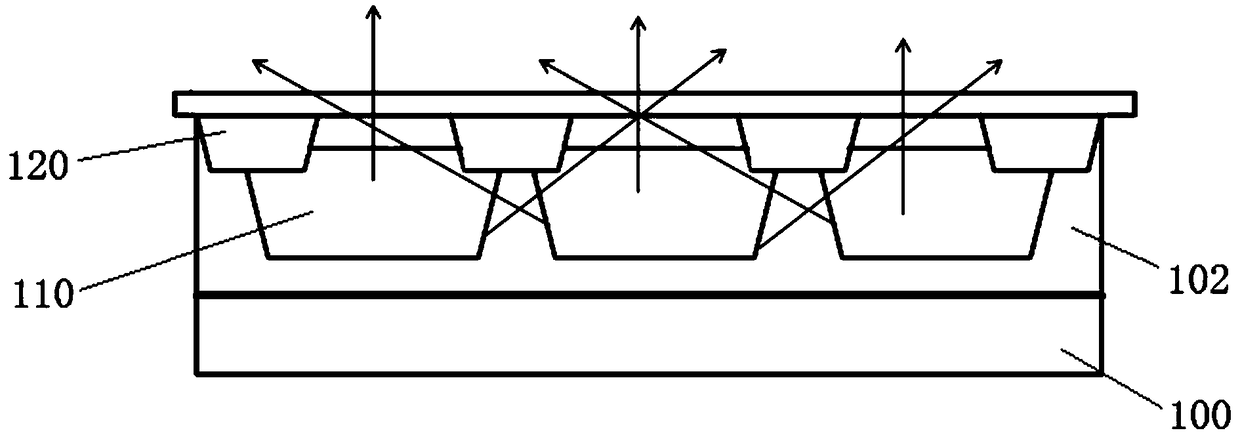
technical field [0001] The invention relates to the field of plane display, in particular, a display panel which can be used on OLED, LCD and other plane display devices. Background technique [0002] It is known that QD (Quantum Dots, Quantum Dots) material has a wider absorption peak and a narrower emission peak, so that it can exhibit higher purity in color display, so that when it is used in a display device, it can Improve the display effect of the display device. For example, when it is applied to an LCD, it can effectively improve the color gamut of the LCD, thereby increasing the competitiveness of the LCD panel. [0003] However, there are still many problems to be overcome in the specific implementation. One of them is to solve the problems of color mixing and low light utilization efficiency of quantum dot color resistance (QD Color Filter). [0004] The so-called color mixing problem is, if figure 2 As shown, on the OC (Over Coating, photoresist) layer 102 of...

Claims


Application Information

Patent Timeline
Patent Type & Authority Applications(China)
IPC IPC(8): G02F1/1335G02F1/13357H01L27/32
CPCG02F1/133514G02F1/1336G02F1/133614H10K59/38H10K59/8792G02B5/201H10K2102/331H10K50/865
Inventor 杨超群黄长治
Owner WUHAN CHINA STAR OPTOELECTRONICS TECH CO LTD
Learn More