Thermomagnetic system structure

A system structure, thermal magnetic technology, applied in the direction of protection switch operation/release mechanism, etc., can solve the problem of inaccurate positioning of thermal tripping fixed plate, magnetic tripping fixed plate and tripping backing plate, unstable connection strength and precision, and connection The strength does not meet the requirements and other problems, to achieve the effect of omitting cumbersome procedures, reliable connection, and simplifying the assembly process

Pending Publication Date: 2019-02-26
ZHEJIANG CHINT ELECTRIC CO LTD
View PDF10 Cites 0 Cited by
  • Summary
  • Abstract
  • Description
  • Claims
  • Application Information

AI Technical Summary

Problems solved by technology

However, due to the trend of miniaturization of switching appliances, the thermal magnetic system is often relatively small in size and compact in structure. Not only is the assembly process cumbersome, but it is also prone to inaccurate positioning of the thermal tripping fixing plate, magnetic tripping fixing plate and tripping backing plate. problems, as well as the problem that the connection strength does not meet the requirements, resulting in the thermomagnetic system not being able to trigger the tripping of the switching device when the circuit is abnormal
Moreover, the lever of the magnetic trip module is supported near the thermal trip module through the magnetic trip fixing plate, and the connection strength and accuracy of the lever and the magnetic trip fixing plate itself are very unstable. Under the influence of the high temperature of the thermal trip module The lever can easily come out of the magnetic trip fixing plate, causing the magnetic trip module to fail

Method used


Image

  • Thermomagnetic system structure
  • Thermomagnetic system structure
  • Thermomagnetic system structure

Examples


Embodiment Construction

[0034] The following is attached Figures 1 to 9 The given examples further illustrate the specific implementation of the thermomagnetic system structure of the present invention. The structure of the thermomagnetic system of the present invention is not limited to the description of the following embodiments.

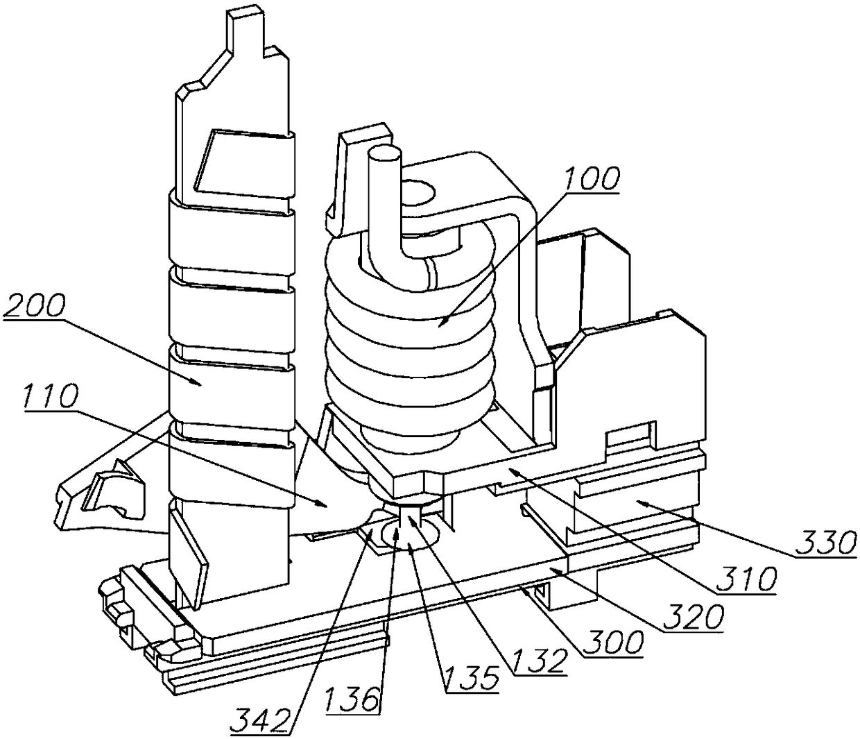
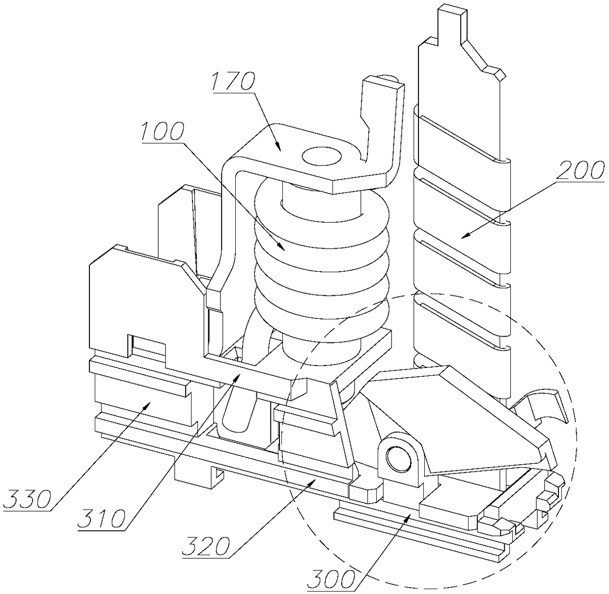
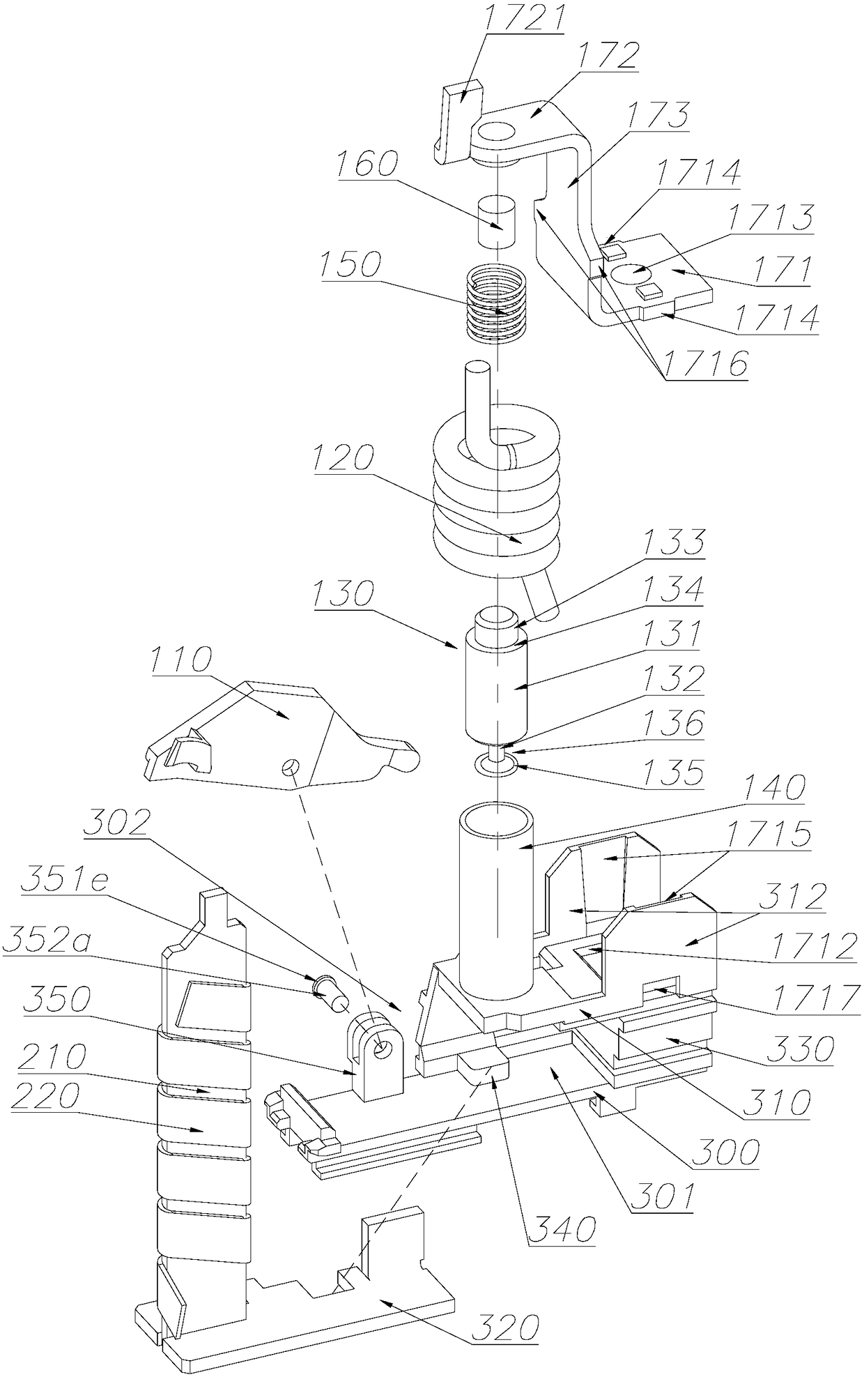
[0035] Such as Figure 1-3 In the shown embodiment, the thermal-magnetic system structure of the present invention includes a magnetic trip module 100 and a thermal trip module 200, the magnetic trip module 100 is arranged on the magnetic trip fixing plate 310, and the thermal trip fixing plate 320 is arranged on the On the thermal trip fixing plate 320, the magnetic trip fixing plate 310 and the thermal trip fixing plate 320 are arranged on the trip backing plate 300, and the thermal trip fixing plate 320 is located on the magnetic trip fixing plate 310 and the trip backing plate 300 between;

[0036] The tripping backing plate 300 is connected to the magnetic trip...


PUM


Abstract

The invention discloses a thermomagnetic system structure, and the structure comprises a magnetic trip module and a thermal trip module. The magnetic trip module is disposed on a magnetic trip fixingplate, and the thermal trip fixing plate is disposed on a thermal trip fixing plate. The magnetic trip fixing plate and the thermal trip fixing plate are disposed on a tripping pad plate, and the thermal tripping fixing plate is located between the magnetic tripping fixing plate and the tripping pad plate. The tripping pad plate is connected with the magnetic tripping fixing plate through a support. The tripping pad plate, the magnetic trip fixing plate and the support form an operation space for fixing the thermal trip fixing plate through enclosing. A fixing mechanism for fixing the thermaltrip fixing plate is disposed at one side of the operation space, and the thermal trip fixing plate is pushed into the operation space from the other side to be fixed on the tripping pad plate by thefixing mechanism. The thermal trip fixing plate is pushed into the operation space from one side to be fixed on the tripping pad plate by the fixing mechanism, so the assembly efficiency is high, andthe magnetic trip fixing plate does not need to be disassembled for directly taking down the thermal trip fixing plate, thereby facilitating maintenance.

Description

technical field [0001] The invention relates to the field of low-voltage electrical appliances, in particular to a thermal-magnetic system structure. Background technique [0002] As an important component of switching appliances, the thermal magnetic system triggers the tripping of the circuit breaker to realize the protection function when the electrical circuit is abnormal, especially for the starter of the motor. The thermal magnetic system includes a magnetic trip module for short circuit protection and for For thermal trip modules with time-delay protection, when assembling a thermal-magnetic system, it is often necessary to stack the thermal trip fixing plate and the magnetic trip fixing plate vertically on the trip pad for positioning, then form a fixed connection, and then pass through the trip pad The plate is fixed to the case of the circuit breaker. However, due to the trend of miniaturization of switching appliances, the thermal magnetic system is often relativ...

Claims


Application Information

Patent Timeline
Patent Type & Authority Applications(China)
IPC IPC(8): H01H71/40
CPCH01H71/40
Inventor 徐胜国胡建国毛承辉江椿龄林铸鑫
Owner ZHEJIANG CHINT ELECTRIC CO LTD
Why Eureka
Try Eureka