Supercharge Your Innovation With Domain-Expert AI Agents!

Magnetic energy transmission device and power generation system therewith

A transmission device and power generation system technology, applied in electromechanical devices, electric brakes/clutches, permanent magnetic clutches/brakes, etc., can solve problems such as low output kinetic energy efficiency and low kinetic energy efficiency

Inactive Publication Date: 2019-02-26
丁金助
View PDF5 Cites 0 Cited by
  • Summary
  • Abstract
  • Description
  • Claims
  • Application Information

AI Technical Summary

Problems solved by technology

[0002] Generally, when the motor drives the generator through the output of kinetic energy, most of it will be consumed during the transmission process, and the efficiency of the output kinetic energy will not be obvious. The main reasons include the loss of conductive wires, the loss caused by the iron core of the rotor, and friction. mechanical loss, and the aforementioned reasons may result in cumulative loss, which is the main reason for the poor efficiency of the overall output kinetic energy

Method used


Image

  • Magnetic energy transmission device and power generation system therewith
  • Magnetic energy transmission device and power generation system therewith
  • Magnetic energy transmission device and power generation system therewith

Examples


Embodiment Construction

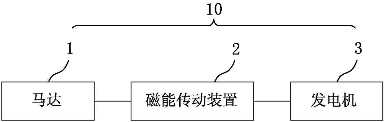
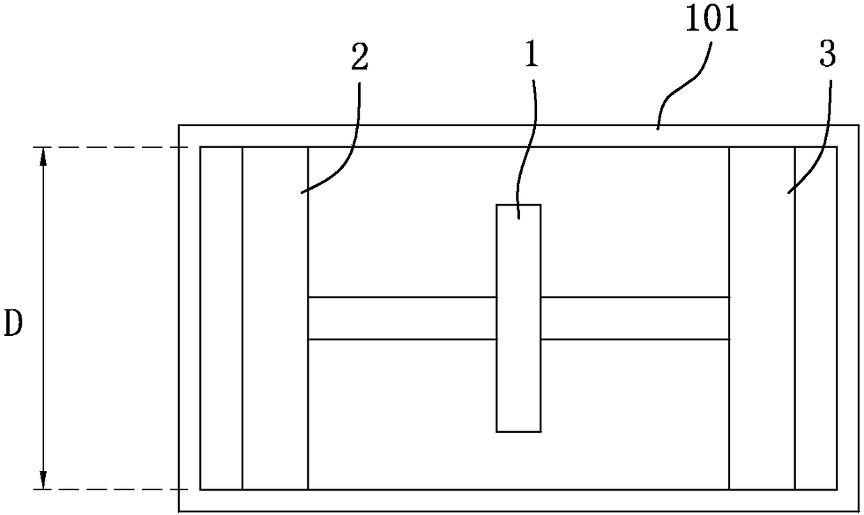
[0022] refer to figure 1 and figure 2 , an embodiment of the power generation system of the present invention includes a housing 101, a motor 1 housed in the housing 101, a magnetic energy transmission device 2 housed in the housing 101 and linked with the motor 1, and a motor 1 housed in the housing 101 and the generator 3 linked with the motor 1.

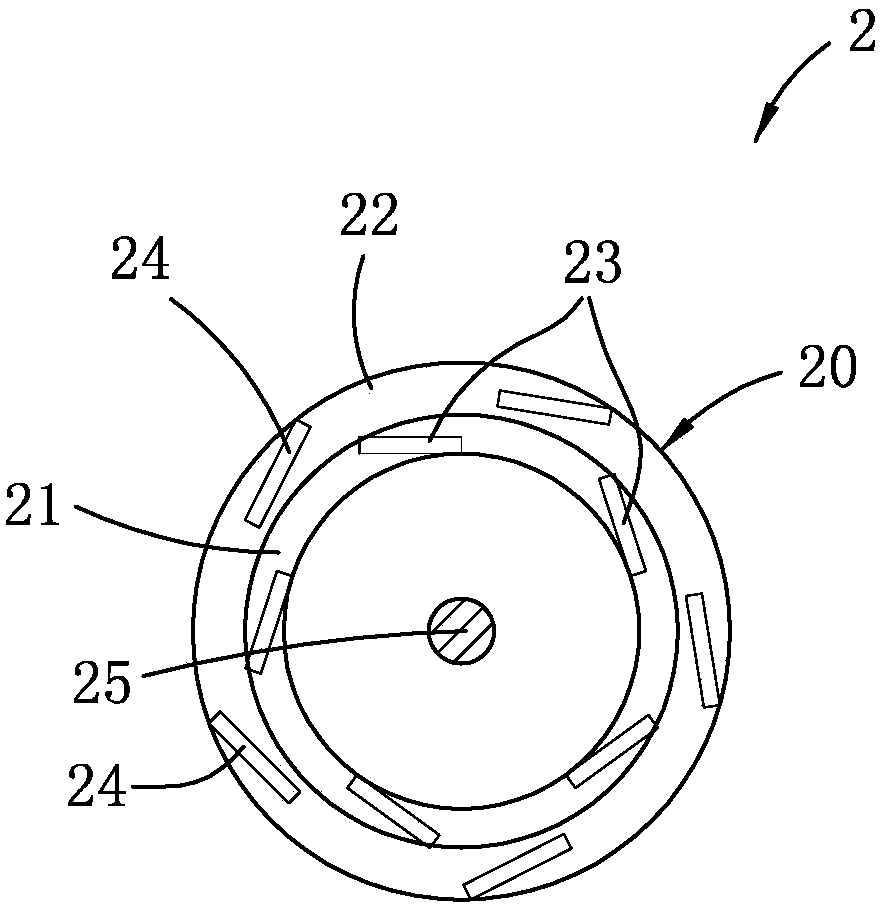
[0023] refer to Figure 2 to Figure 4 , The magnetic energy transmission device 2 includes a first ring 21 , a second ring 22 , five first magnetic bodies 23 , five second magnetic bodies 24 and a shaft 25 . Both the first ring member 21 and the second ring member 22 are made of non-magnetic material. In this embodiment, they are made of plastic, but not limited thereto. The second ring 22 is sleeved on the outer periphery of the first ring 21. In this embodiment, the second ring 22 is fixed on a pair of legs (not shown). The second ring 22 and The first ring part 21 cooperates to define a ring body 20 , and the first ring pa...


PUM


Abstract

The invention discloses a magnetic energy transmission device, and the device is suitable to be connected with a motor. The device comprises a first annular part, a shaft rod, a second annular part, aplurality of first magnets, and a plurality of second magnets. The shaft rod passes through the first annular part and is connected with the motor. The second annular part sleeves the periphery of the first annular part, and the second annular part and the first annular part cooperate to define an annular body. The first annular body can rotate relative to the second annular body. The first magnets are annularly disposed in the annular body at intervals, and are adjacent to the first annular part. The second magnets are annularly disposed in the annular body at intervals, and are adjacent tothe second annular part. The magnetism of each second magnet is different from the magnetism of the adjacent first magnet.

Description

technical field [0001] The invention relates to a magnetic energy transmission device, in particular to a magnetic energy transmission device and a power generation system capable of reducing energy loss during transmission. Background technique [0002] Generally, when the motor drives the generator through the output of kinetic energy, most of it will be consumed during the transmission process, and the efficiency of the output kinetic energy will not be obvious. The main reasons include the loss of conductive wires, the loss caused by the iron core of the rotor, and friction. mechanical loss, and the aforementioned reasons may result in cumulative loss, which is the main reason for the poor efficiency of the overall output kinetic energy. [0003] Based on the above reasons, how to design a magnetic energy transmission device that can reduce output loss and enhance output efficiency is an important topic. Contents of the invention [0004] Therefore, one of the objecti...

Claims


Application Information

Patent Timeline
IPC IPC(8): H02K49/10H02K7/10H02K7/18
CPCH02K7/10H02K7/1807H02K49/106
Inventor 丁金助
Owner 丁金助
Features
  • R&D
  • Intellectual Property
  • Life Sciences
  • Materials
  • Tech Scout
  • Unparalleled Data Quality
  • Higher Quality Content
  • 60% Fewer Hallucinations
Learn More