Multifunctional pot

A multifunctional pot and pot body technology, which is applied in the field of kitchen utensils, can solve the problem that the skin color and taste are not crispy and delicious

Pending Publication Date: 2019-03-01
GUANGDONG SHUNDE OUNING ELECTRICAL APPLIANCE CO LTD
View PDF7 Cites 11 Cited by
  • Summary
  • Abstract
  • Description
  • Claims
  • Application Information

AI Technical Summary

Problems solved by technology

However, after pressure cooking, the skin color and taste of the food cannot reach the crispy, interesting and delicious feeling. If it can be baked, the food will be full of color, aroma and taste, plus the functions of health and nutrition, and will be popular among consumers. Loved by readers, huge market potential
Existing pressure cookers only have the function of pressure cooking. Similarly, existing air fryers only have the function of cooking food with hot air. At present, there is no product that has both pressure and air frying functions.

Method used


Image

  • Multifunctional pot
  • Multifunctional pot
  • Multifunctional pot

Examples


Embodiment 1

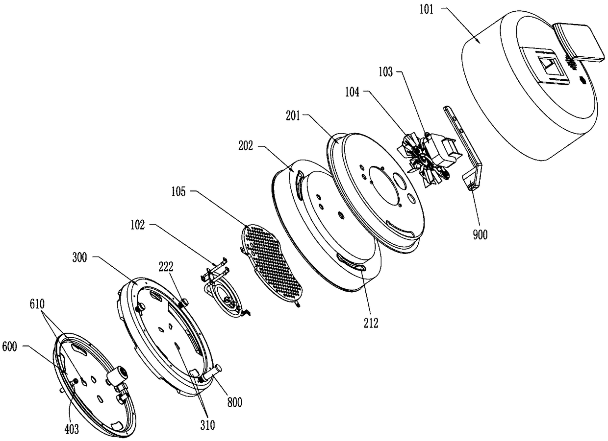
[0038] like figure 1 As shown, the present invention provides a multifunctional pot. The multifunctional pot is provided with a pot body 109 and an upper cover assembly, and the pot body 109 and the upper cover assembly are rotatably connected. A thermal insulation component 200 , a heating component 102 and a wind power component 103 are arranged on the upper cover component.

[0039] like Figure 4 As shown, the heat shield assembly 200 is provided with a first heat shield 201 and a second heat shield 202, the first heat shield 201 and the second heat shield 202 are connected to each other, the first heat shield 201 and the second heat shield The heat shield 202 is fixedly connected with the upper shell 101 provided with the upper cover assembly.

[0040] The wind power assembly 103 is provided with a driving motor fixedly arranged on the first heat shield 201 , the drive shaft of the drive motor passes through the first heat shield 201 and the second heat shield 202 , and...

Embodiment 2

[0049] This embodiment is similar to Embodiment 1, the difference is that in this embodiment, the air duct 610 is provided with two parts on the first member 600, which are respectively the air inlet duct and the air outlet duct, and the air inlet duct and the air outlet duct. The air outlet ducts are concentrically distributed on the first component 600 . The air inlet channel is arranged at the edge of the first member 600 , and the air outlet channel is arranged at the center of the first member 600 .

Embodiment 3

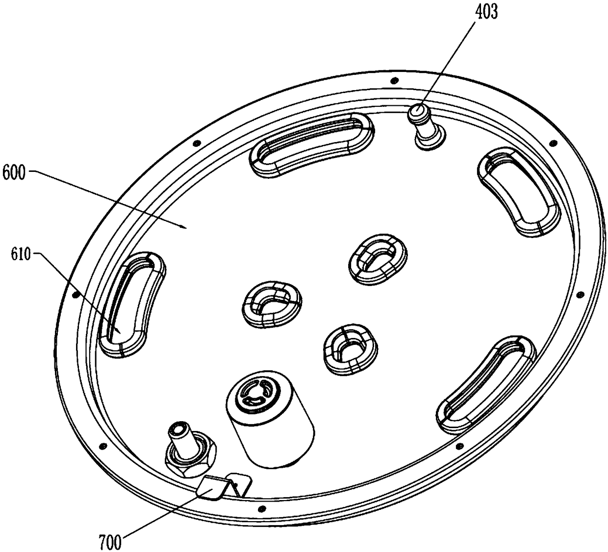
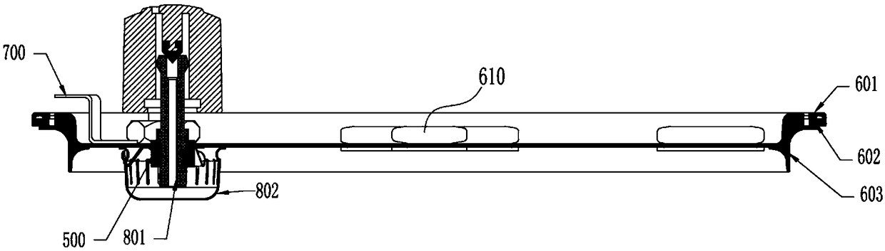
[0051] This embodiment is similar to Embodiment 1, the difference is that in this embodiment, as image 3 As shown, the first component 600 is provided with a component A601 and a component B602 , and the component A601 and the component B602 are connected through a sealing gasket 603 . The sealing gasket 603 has an arc structure, through which the sealing connection between the first member 600 and the inner pot 106 is realized.

[0052] like figure 2 and as image 3 As shown, the first member 600 is provided with the second limit mechanism 403 and the first limit mechanism 700, the heat insulation assembly 200 is provided with the second limit member 203, and the second limit mechanism 403 can be connected with the second limit mechanism. The member 203 is fitted and connected to realize the connection between the first member 600 and the second heat shield 202 .

[0053] The first limiting mechanism 700 is fixedly connected with the component A601, the first limiting me...


PUM


Abstract

The invention relates to a kitchen utensil, in particular to a multifunctional pot. The multifunctional pot comprises a pot body and an upper cover assembly, wherein the upper cover assembly is provided with a heat generating assembly and a wind power assembly. The multifunctional pot is provided with a first member cooperating with the upper cover assembly, the first member is provided with air ducts, the first member seals or unseals the pot body through the state change of the air ducts, the first member can release pressure when the pressure in the pot body exceeds a threshold value, functions of a pressure cooker and an air fryer are integrated, and switching of functions of the pressure cooker and the air fryer can be conveniently realized.

Description

technical field [0001] The present invention relates to a kitchen utensil, more specifically, to a multifunctional pot. Background technique [0002] The current consumers are constantly pursuing healthy cooking and food pursuits with complete color, aroma and taste. Pressure cooking has pressure penetration and can reach a certain temperature. The market generally believes that this function can achieve healthy and nutritious cooking. However, after pressure cooking, the skin color and taste of the food cannot reach the crispy, interesting and delicious feeling. If it can be baked, the food will be full of color, aroma and taste, plus the functions of health and nutrition, and will be popular among consumers. Loved by readers, the market potential is huge. Existing pressure cooker only has the function of pressure cooking, and similarly, existing air fryer also only has the function of cooking food with hot air, and there is no product that has both pressure and air frying...

Claims


Application Information

Patent Timeline
Patent Type & Authority Applications(China)
IPC IPC(8): A47J27/08A47J37/06
CPCA47J27/08A47J27/0802A47J37/0629A47J37/0664A47J37/0641A47J27/086A47J27/09
Inventor 黄振雄杨云
Owner GUANGDONG SHUNDE OUNING ELECTRICAL APPLIANCE CO LTD
Why Eureka
Try Eureka