Out-plane piezoelectric type hemispheric micro-gyroscope and preparation method thereof

A micro-gyroscope and hemispherical technology, applied in gyroscope/steering sensing equipment, gyro effect for speed measurement, piezoelectric device/electrostrictive device, etc., can solve the problem of difficult to realize highly symmetrical electrode processing and interference micro-gyroscope control and detection, doping technology and limited production accuracy, to achieve the effect of mass production, large effective vibration displacement, and high degree of integration

Active Publication Date: 2015-09-09
SHANGHAI JIAO TONG UNIV
View PDF7 Cites 8 Cited by
  • Summary
  • Abstract
  • Description
  • Claims
  • Application Information

AI Technical Summary

Problems solved by technology

However, the manufacturing precision of doping technology is limited, and it is difficult to realize the processing of highly symmetrical electrodes; the capacitive micro-electrodes distributed around are relatively close to each other, and there is a certain parasitic capacitance between adjacent electrodes, which interferes with the control and detection of micro-gyroscopes and limits its performance. Ultimate precision; the thickness of the micro-resonator produced by deposition is limited, generally only at the micron level, and the controllability is poor; the production of the gyroscope requires multiple photolithography masks, and the process is complicated, which is not conducive to the realization of high precision

Method used


Image

  • Out-plane piezoelectric type hemispheric micro-gyroscope and preparation method thereof
  • Out-plane piezoelectric type hemispheric micro-gyroscope and preparation method thereof
  • Out-plane piezoelectric type hemispheric micro-gyroscope and preparation method thereof

Examples


Embodiment 1

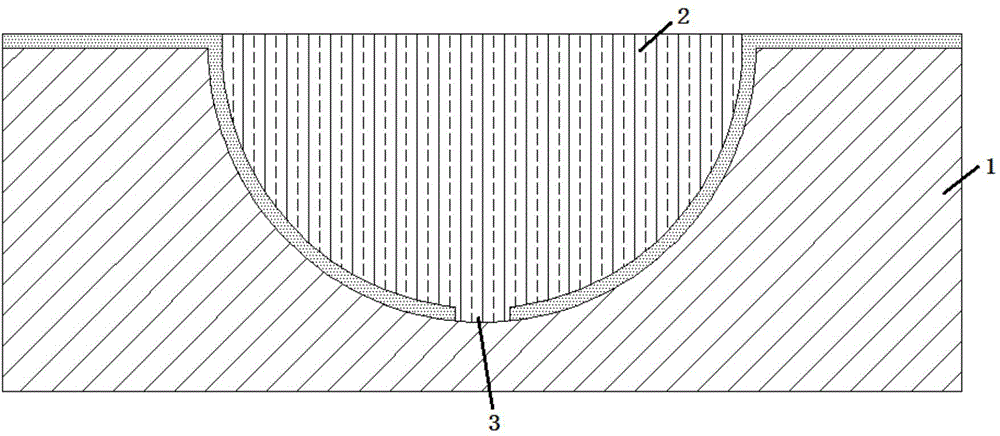
[0038] Such as figure 2 As shown, the present embodiment provides an out-of-plane piezoelectric hemispherical micro-gyroscope, including:

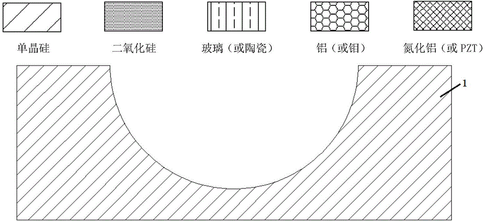
[0039] A monocrystalline silicon substrate 1 with a hemispherical groove;

[0040] A miniature hemispherical harmonic oscillator 2;

[0041] a cylindrical support column 3;

[0042] a common electrode 4;

[0043] Eight uniformly distributed thin-film piezoelectric bodies 5;

[0044] Eight evenly distributed signal electrodes 6;

[0045]Wherein: the surface provided with the hemispherical groove is the upper surface of the single crystal silicon substrate 1, and the opposite surface is the lower surface; the upper end of the cylindrical support column 3 is connected to the micro-hemispherical resonator 2, and the lower end is connected to the micro-spherical resonator 2. The single crystal silicon substrate 1 is connected; the cylindrical support column 3 and the miniature hemispherical resonator 2 are located in the hemispherical gro...

Embodiment 2

[0057] Such as Figure 1(a)-Figure 1(f) As shown, the present embodiment provides a method for preparing an out-of-plane piezoelectric hemispherical micro-gyroscope, including the following steps:

[0058] The first step, as shown in FIG. 1(a), is to clean the single crystal silicon substrate 1, grow a silicon nitride layer, and perform steps such as coating, photolithography, development, RIE etching, and degumming on the silicon nitride layer. A circular opening is opened on the top, and a hemispherical groove with a radius of 350-650 μm is prepared on the single crystal silicon substrate 1 through steps such as HNA etching and hot phosphoric acid etching;

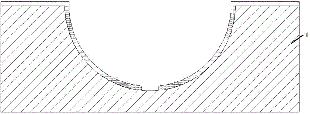
[0059] The second step, as shown in Figure 1(b), is to thermally oxidize and grow a silicon dioxide layer with a thickness of 1-10 μm on the basis of the first step, through the steps of coating, photolithography, development, etching, and degumming. Making a circular opening with a radius of 20-50 μm at the bottom of th...

Embodiment 3

[0066] Basically the same as embodiment 1 and embodiment 2, the difference is:

[0067] Such as image 3 As shown, in this embodiment, the material of the micro-hemispherical resonator 2 and the cylindrical support column 3 is metallic glass or metal, and the micro-hemispherical resonator 2 can be used as the micro-hemispherical resonator 2 and the common electrode at the same time. 4. There is no need to make an additional common electrode 4 , and the thin-film piezoelectric body 5 is evenly distributed on the upper surface of the miniature hemispherical resonator 2 at this time.

[0068] In the preparation method of the gyroscope with this structure, the fourth step is omitted in the preparation method steps of Example 2, that is, the fifth step is based on the third step by sputtering an aluminum nitride film or a PZT film.


PUM

PropertyMeasurementUnit
radiusaaaaaaaaaa
thicknessaaaaaaaaaa
radiusaaaaaaaaaa

Abstract

The invention provides an out-plane piezoelectric type hemispheric micro-gyroscope and a preparation method thereof. The out-plane piezoelectric type hemispheric micro-gyroscope comprises a monocrystalline silicon substrate, a miniature hemispheric harmonic oscillator, a central fixed support pillar, a common electrode, a uniformly distributed film piezoelectric body and a uniformly distributed signal electrode. According to the invention, the hemispheric structure is adopted as a harmonic oscillator, so that great effective vibration displacement is obtained, and detection effect for Coriolis effect can be enhanced; the common electrode, the film piezoelectric body and the signal electrode are manufactured by adopting an MEMS planar process, so that the manufacturing precision is high, and the structural degree of symmetry of the micro-gyroscope can be improved; the out-plane driving and the detection method are adopted, so that interconversion between out-plane force and in-plane can be realized, and Coriolis effect vertical to the direction of the substrate can be detected; the piezoelectric type driving and the detection method are adopted, miniature capacitance space needed by electrostatic micro-gyroscope is not needed, and meanwhile, the problems of stray capacitance, electrostatic adherence and the like are avoided; the technology is simple, the integrated degree is high, and batch production can be realized.

Description

technical field [0001] The invention relates to a vibrating gyroscope in the field of micro-electromechanical technology, in particular to an out-of-plane piezoelectric hemispherical micro-gyroscope and a preparation method thereof. Background technique [0002] Gyroscope is an inertial device that can detect the angle or angular velocity of the carrier, and it plays a very important role in the fields of attitude control, navigation and positioning. With the development of national defense technology and aviation and aerospace industries, the requirements of inertial navigation systems for gyroscopes are also developing in the direction of low cost, small size, high precision, multi-axis detection, high reliability, and adaptability to various harsh environments. Therefore, the importance of MEMS micro-gyro is self-evident. In particular, the micro-hemispherical resonant gyroscope, as an important research direction of the MEMS micro-gyroscope, has become a research hotspo...

Claims


Application Information

Patent Timeline
Patent Type & Authority Applications(China)
IPC IPC(8): G01C19/5691B81B3/00B81C1/00
CPCB81B3/00B81C1/00G01C19/5691
Inventor 张卫平唐健汪濙海刘亚东孙殿竣邢亚亮陈文元
Owner SHANGHAI JIAO TONG UNIV
Why Eureka
Try Eureka