Eureka AIR delivers breakthrough ideas for toughest innovation challenges, trusted by R&D personnel around the world.

Suture equipment for insert and suture method of equipment

A suture equipment and implant technology, applied in the field of medical devices, can solve the problems of low production efficiency, failure to meet the suture requirements of the reinforcement layer and the bare stent, high labor input costs, etc., and achieve the effect of precise suture position

Active Publication Date: 2019-03-01
MICROPORT SINICA CO LTD
View PDF8 Cites 4 Cited by
  • Summary
  • Abstract
  • Description
  • Claims
  • Application Information

AI Technical Summary

Problems solved by technology

[0003] Due to the limitations of the stitching process of the reinforcement layer and the bare bracket, such as precise positioning, small needle holes, three-dimensional stitching, and special and firm thread node knotting methods, the current manual stitching method is mainly used, which will lead to difficulty in product quality consistency. Guaranteed, and manual sewing makes the labor input cost higher and the production efficiency lower
On the other hand, due to the structural characteristics and quality requirements of the covered stent, as well as its roughly tubular shape, the automatic suture equipment in the traditional industrial sewing machine system cannot meet the suture requirements of the reinforcement layer and the bare stent

Method used


Image

  • Suture equipment for insert and suture method of equipment
  • Suture equipment for insert and suture method of equipment
  • Suture equipment for insert and suture method of equipment

Examples


Embodiment Construction

[0048] In order to facilitate the understanding of the present invention, the present invention will be described more fully below with reference to the associated drawings. Preferred embodiments of the invention are shown in the accompanying drawings. However, the present invention can be embodied in many different forms and is not limited to the embodiments described herein. On the contrary, these embodiments are provided to make the understanding of the disclosure of the present invention more thorough and comprehensive.

[0049] It should be noted that when an element is referred to as being “fixed” to another element, it can be directly on the other element or there can also be an intervening element. When an element is referred to as being "connected to" another element, it can be directly connected to the other element or intervening elements may also be present. When an element is referred to as being "on" another element, it can be directly on the other element or i...


PUM


Abstract

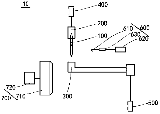
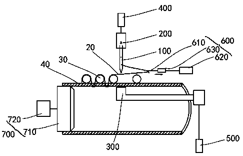
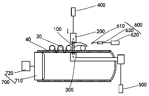
The invention discloses suture equipment for an insert. The equipment comprises a dual-head needle, a control component, a first machine needle driving assembly, a second machine needle driving assembly and a conveying assembly; the first machine needle driving assembly, the second machine needle driving assembly, the conveying assembly and the control component are in communication connection, and the control component is used for controlling motion of the first machine needle driving assembly, the second machine needle driving assembly and the conveying assembly; the dual-head needle is provided with a needle hole for a suture thread to penetrate through; the first machine needle driving assembly and the second machine needle driving assembly are arranged at the two opposite sides of thedual-head needle respectively, a suture gap for a to-be-sutured part to pass through is formed between the first machine needle driving assembly and the second machine needle driving assembly, and the first machine needle driving assembly and the second machine needle driving assembly can clamp and release the dual-head needle and drive the dual-head needle to reciprocate along a first path so that the to-be-sutured part can be sutured. According to the suture equipment, the labor cost can be reduced, and the production efficiency can be improved.

Description

technical field [0001] The invention relates to the field of medical devices, in particular to a suturing device for implants and a suturing method thereof. Background technique [0002] Implants are commonly used in minimally invasive interventional medical devices to treat certain diseases of human organs, such as the use of covered stents to treat diseases such as thoracic / abdominal aortic aneurysms. The implant generally includes a bare stent and a reinforcement layer at least partially covering the bare stent, and the reinforcement layer and the bare stent need to be stitched into shape. [0003] Due to the limitations of the stitching process of the reinforcement layer and the bare bracket, which requires precise positioning, small needle holes, three-dimensional stitching, and special and firm thread node knotting methods, the current manual stitching method is mainly used, which will lead to difficulties in product quality consistency. Guaranteed, and manual sewing ...

Claims


Application Information

Patent Timeline
IPC IPC(8): A61B17/00A61B17/04A61B17/072D05B23/00
CPCA61B17/00A61B17/04A61B17/072D05B23/00
Inventor 周磊李维旭束宇婷张劼
Owner MICROPORT SINICA CO LTD
Why Eureka
Eureka Blog
Learn More