Driving device for automatically lifting presser foot and trimming thread in sewing machine

A driving device and sewing machine technology, applied in the sewing machine's thread cutting mechanism, sewing machine control device, sewing machine components, etc., can solve the problem of inability to accurately control the lifting of the presser foot, inability to realize thread trimming drive at the same time, and high labor intensity of the operator, etc. problems, achieve the effect of improving sewing efficiency and effect, simple structure and high degree of automation

Active Publication Date: 2020-08-14
浙江杰克智能缝制科技有限公司
View PDF8 Cites 5 Cited by
  • Summary
  • Abstract
  • Description
  • Claims
  • Application Information

AI Technical Summary

Problems solved by technology

When the presser foot lifting device of an industrial sewing machine adopts a manual device, it is often necessary to press the knee against the joystick assembly of the sewing machine to lift the presser foot when feeding, and this has a problem: It is necessary to lean the knee against the joystick assembly of the sewing machine, so the labor intensity of the operator is high and it is easy to get tired
[0005] The automatic presser foot lifting mechanism of the lockstitch sewing machine mentioned in the above patent documents cannot realize the driving of the thread trimmer at the same time, and its function is not stable enough, it is prone to jamming, and it cannot accurately control the lifting of the presser foot, which is inconvenient during use

Method used


Image

  • Driving device for automatically lifting presser foot and trimming thread in sewing machine
  • Driving device for automatically lifting presser foot and trimming thread in sewing machine
  • Driving device for automatically lifting presser foot and trimming thread in sewing machine

Examples


Embodiment Construction

[0038] The following are specific embodiments of the present invention and the technical solution of the present invention is further described in conjunction with the accompanying drawings, but the present invention is not limited to the following embodiments.

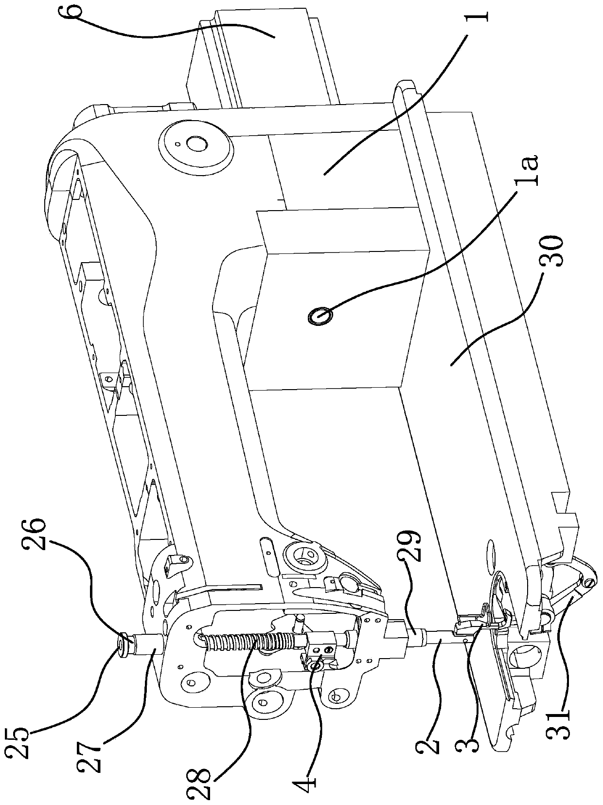
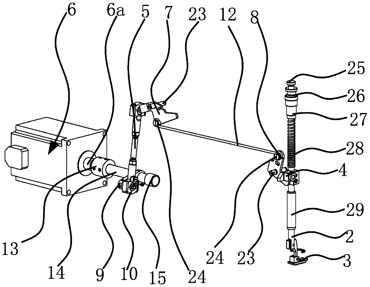
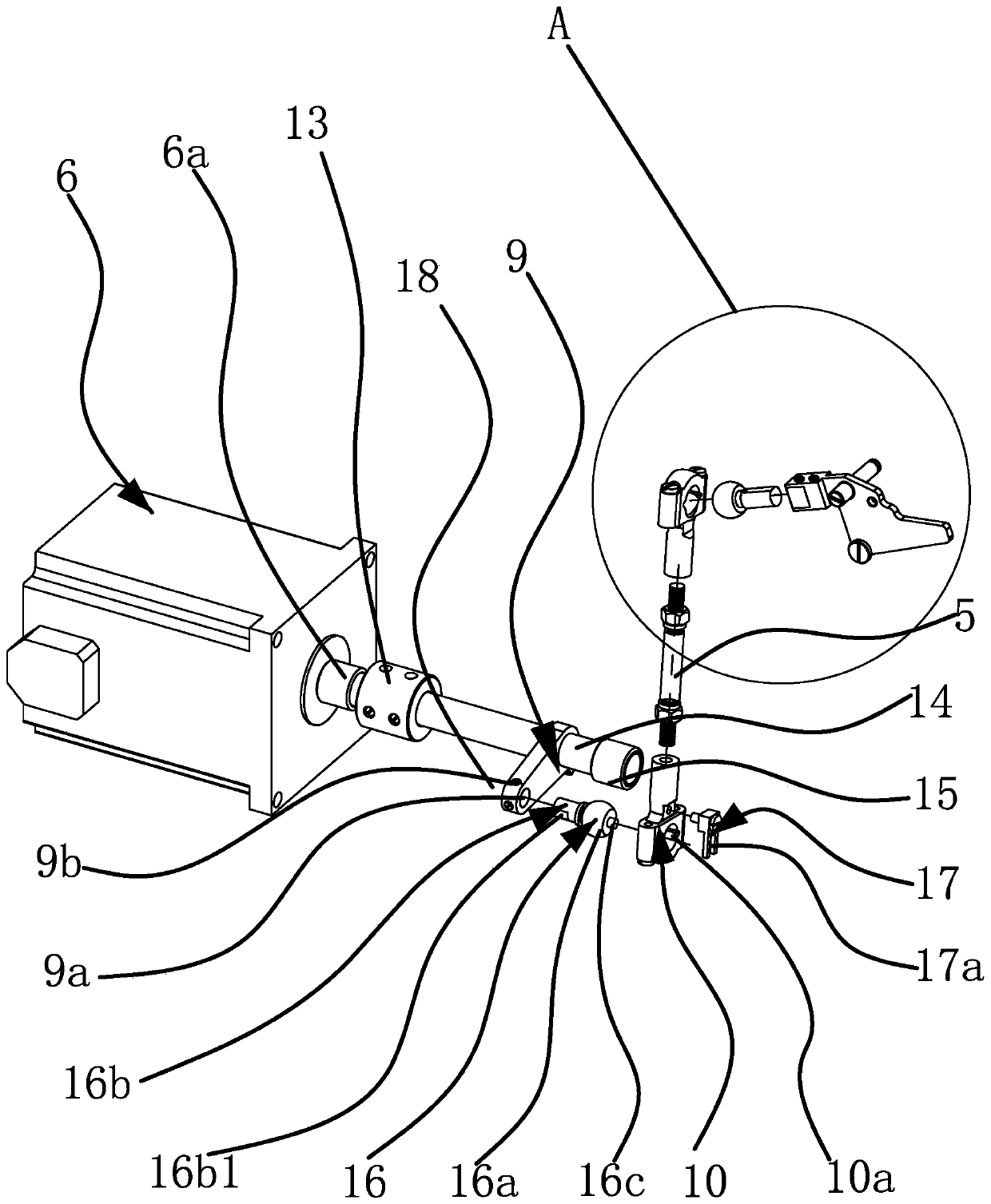
[0039] Such as figure 1 , figure 2 with Figure 9 As shown, the sewing machine includes a base plate 30, a casing 1 fixed on the base plate 30, a vertically arranged pressing rod 2 and a presser foot 3 arranged at the lower end of the pressing rod 2, and a guide frame is fixedly arranged on the pressing rod 2. 4. The bottom of the bottom plate 30 is provided with a thread trimmer assembly 31; the driving device includes a lifting rod 5, a driving part 6 fixed on the casing 1, and a left lever 7 and a right lever 8 respectively hinged on the casing 1, and the driving part The output shaft 6a of 6 is connected with the swing crank 9 that can swing under the drive of the driver 6, the lifting rod 5 is vertically arran...


PUM


Abstract

The invention provides a driving device for automatically lifting a presser foot and trimming a thread in a sewing machine, and belongs to the technical field of garment manufacturing equipment. The technical problem that an existing driving device for automatically lifting the presser foot and trimming the thread in the sewing machine is unstable in function is solved. The sewing machine comprises a bottom plate, a machine shell, a pressing rod and the presser foot, wherein a guide frame is fixedly arranged on the pressing rod, and a thread trimming assembly is arranged at the bottom of the bottom plate. The driving device comprises a lifting pull rod, a driving part, a left lever and a right lever, wherein a swing crank is connected to an output shaft of the driving part; the lower end of the lifting pull rod is in spherical hinge joint with the outer end of the swing crank through a lower spherical connecting rod; the upper end of the lifting pull rod is in spherical hinge joint with one end of the left lever through an upper spherical connecting rod; the other end of the left lever is connected with one end of the right lever through a lifting connecting rod; the other end of the right lever can abut against the lower side of the guide frame; and the outer end of the swing crank is connected with the thread trimming assembly. The driving device is stable in function, the lifting height of the presser foot can be accurately controlled, and meanwhile the thread trimming function is achieved.

Description

technical field [0001] The invention belongs to the technical field of garment manufacturing equipment, and relates to a sewing machine, in particular to a driving device for automatically lifting the presser foot and cutting the thread in the sewing machine. Background technique [0002] With the rapid development of science and technology, the degree of mechanization of clothing manufacturing is getting higher and higher. In the field of clothing manufacturing technology, there are many sewing equipment mainly industrial sewing machines, such as lockstitch sewing machines, overlock sewing machines, interlock sewing machines, etc. At present, when the industrial sewing machine is feeding, the operation of lifting and pressing the presser foot is generally performed manually or automatically through an electronic control signal, that is, the presser foot lifting device of the industrial sewing machine is a manual device or an automatic device. When the presser foot lifting d...

Claims


Application Information

Patent Timeline
Patent Type & Authority Applications(China)
IPC IPC(8): D05B29/02D05B65/00D05B69/10
CPCD05B29/02D05B65/00D05B69/10
Inventor 张鑫媛李朝国祝书伟
Owner 浙江杰克智能缝制科技有限公司
Why Eureka
Try Eureka