Cutting machine capable of electrified work

A technology for live operation and cutting machine, which is applied to shearing devices, hand-held metal shearing equipment, overhead line/cable equipment, etc. Accidents, the effect of ensuring efficiency and quality

Pending Publication Date: 2019-03-01
国网河南省电力公司巩义市供电公司 +3
View PDF8 Cites 2 Cited by
  • Summary
  • Abstract
  • Description
  • Claims
  • Application Information

AI Technical Summary

Problems solved by technology

During the cable laying and wiring process, the equipment is fastened by bolts. According to the erection site, further cutting operations are often required for the fastening bolts. The existing cutting machine has a complex structure, is heavy and inconvenient to carry.

Method used


Image

  • Cutting machine capable of electrified work
  • Cutting machine capable of electrified work

Examples


Embodiment Construction

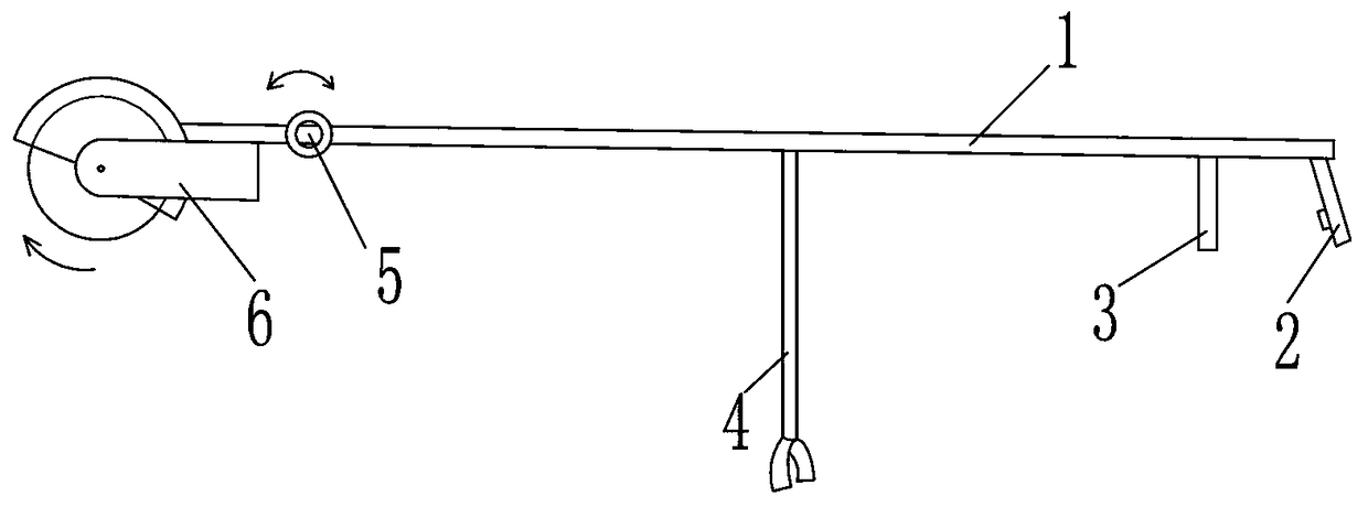
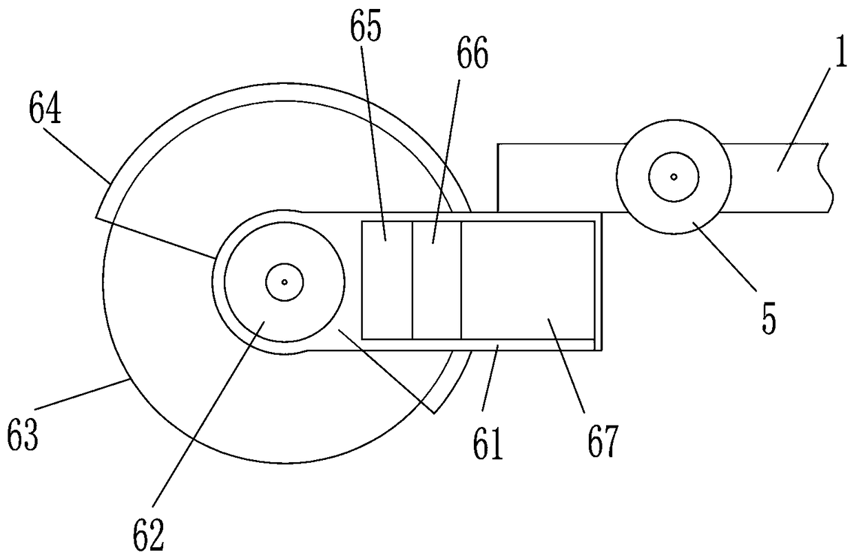
[0018] Numbers in the figure, number 1 stands for insulating rod, number 2 stands for switch handle, number 3 stands for stable handle, number 4 stands for fork support rod, number 5 stands for angler, number 6 stands for cutting mechanism, and number 61 stands for insulating casing , the symbol 62 represents the driving motor, the symbol 63 represents the cutting disk, the symbol 64 represents the insulating shield of the cutting disk, the symbol 65 represents the motor controller, the symbol 66 represents the communication circuit module, and the symbol 67 represents the power supply.

[0019] The present invention will be described in further detail below in conjunction with the accompanying drawings and technical solutions, and the implementation of the present invention will be described in detail through preferred embodiments, but the implementation of the present invention is not limited thereto.

[0020] Aiming at the problems that many operations are not changed in the...


PUM

PropertyMeasurementUnit
lengthaaaaaaaaaa

Abstract

The invention relates to the field of auxiliary equipment for cable erection construction operation, in particular to a cutting machine capable of electrified work. The machine comprises a supportingassembly, a driving motor, a power source and a cutting disc, wherein the power source provides electric energy for the driving motor, the supporting assembly comprises an insulating rod and a switchhandle arranged at one end of the insulating rod, and a knob key used for controlling the driving motor is arranged on the switch handle; and the other end of the insulating rod is connected with an insulating rod extending part through a corner device, the insulating rod extending part is provided with an insulating machine shell used for fixing the driving motor and the power source, the outputshaft of the driving motor is in transmission connection with a rotating shaft of the cutting disc, and a cutting disc insulating protective cover is further fixedly arranged on the insulating machineshell. According to the machine, the structure is simple, design is novel and reasonable, the insulating rod, the switch handle and the corner device cooperate with one another, so that phase-to-phase or phase-to-earth effective distance can be reduced during operation, short circuit accidents are avoided, the angle of the insulating rod and the angle of the operation cutting disc are adjusted conveniently on site according to the operation requirements through the corner device, so that the cutting operation efficiency and the cutting quality are ensured.

Description

technical field [0001] The invention relates to the field of auxiliary equipment for working on cable rack facilities, in particular to a cutting machine capable of live work. Background technique [0002] Wire and cable are used to transmit electric (magnetic) energy, information and wire products to realize electromagnetic energy conversion. In the broad sense, wires and cables are also referred to as cables for short. In the narrow sense, cables refer to insulated cables, which can be defined as: a collection composed of the following parts; one or more insulated cores, and their respective possible coatings. The protective layer and the outer sheath, the cable can also have additional uninsulated conductors, which are mostly erected in the air or installed underground or underwater for telecommunications or power transmission. During the cable laying and wiring process, the equipment is fastened by bolts. According to the erection site, further cutting operations are of...

Claims


Application Information

Patent Timeline
Patent Type & Authority Applications(China)
IPC IPC(8): B23D29/00H02G1/02
CPCH02G1/02B23D29/00
Inventor 吴超锋海岳王磊王红涛郑芳李继红邵昱石磊张天宇
Owner 国网河南省电力公司巩义市供电公司
Why Eureka
Try Eureka