
Rotor core shaft milling tooth fixture

A rotor core and tooth milling technology, which is applied in the manufacture of stator/rotor body, clamping, gear teeth, etc., can solve problems such as difficult to ensure clamping accuracy and complicated fixture operation, and achieve the effect of ensuring clamping accuracy and convenient processing

Pending Publication Date: 2019-03-01
铜陵长江电动工具二厂
View PDF0 Cites 0 Cited by
  • Summary
  • Abstract
  • Description
  • Claims
  • Application Information

AI Technical Summary

Problems solved by technology

[0003] The purpose of the present invention is to solve the problem of complex operation and difficulty in ensuring the clamping accuracy of existing fixtures during processing

Method used


Image

  • Rotor core shaft milling tooth fixture
  • Rotor core shaft milling tooth fixture
  • Rotor core shaft milling tooth fixture

Examples


Embodiment Construction

[0014] Below in conjunction with accompanying drawing, the present invention will be further described.

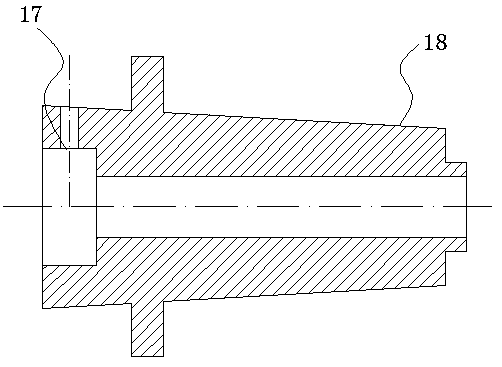
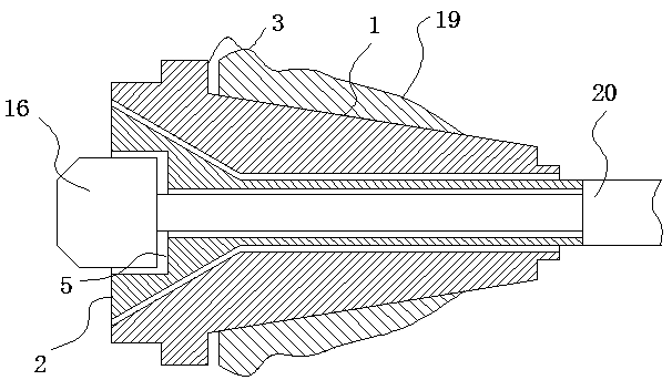
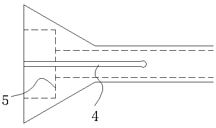
[0015] General embodiment: rotor mandrel gear milling fixture, including a fixed sleeve 1 and a clamping sleeve 2, the fixed sleeve is provided with a through hole, and one side of the fixed sleeve in the length direction is provided with a bell mouth connected with the through hole, close to the bell mouth The radial outer edge of the fixed sleeve protrudes to form a first step 3, one side of the clamping sleeve in the length direction is adapted to the shape of the bell mouth of the fixed sleeve, and this side is provided with a long groove 4 along the outer edge, and this side A second step 5 is arranged inside the clamping sleeve, the other side of the clamping sleeve in the length direction passes through the through hole in the fixed sleeve and the end of the other side of the clamping sleeve in the length direction is located outside the end surface of the other side...


PUM


Abstract

The invention discloses a rotor core shaft milling tooth fixture. The rotor core shaft milling tooth fixture is characterized in that the rotor core shaft milling tooth fixture comprises a fixing sleeve and a clamping sleeve, wherein a through hole is formed in the fixing sleeve, and a bell mouth communicating with the through hole is formed in one side of the fixing sleeve in the length direction; a first step is arranged on an outer edge protrusion in the radial direction of the fixing sleeve close to the bell mouth, the shape of the bell mouth of the fixing sleeve is matched with one side of the clamping sleeve in the length direction, a long groove is formed in the side of the clamping sleeve along an outer edge, and a second step is arranged in the clamping sleeve on the side; and theside, in the length direction, of the clamping sleeve penetrates through the through hole in the fixing sleeve, and the end part of the other side, in the length direction, of the clamping sleeve islocated on the exterior of end surface of the other side, in the length direction, of the fixing sleeve. After the structure is adopted, before the rotor core shaft milling tooth fixture is used, theclamping sleeves with different specifications are prepared according to motor rotor shaft with different lengths. The fixture is installed on a milling machine, a fixing sleeve is installed on a mainshaft of the milling machine, a pull rod drives the clamping sleeve to be in rectilinear motion to clamping a workpiece, the clamping accuracy is ensured, and large quantities of products can be processed conveniently.

Description

technical field [0001] The invention relates to a gear milling fixture for a rotor core shaft. Background technique [0002] The slender rotor mandrel requires the use of fixtures during tooth milling and cutting. Existing fixtures such as figure 1 As shown: a clamping hole is set in the center, one end has a Morse taper, and the other end is radially set with a limit hole. When the existing rotor mandrel is processed by a jig, manually use a jackscrew to pass through the limit. Clamping is achieved behind the hole. This method is easy to slip, easily injures the operator and has low work efficiency. For the processing of relatively slender rotor mandrels, it is difficult to ensure the clamping accuracy, and it is difficult to maintain the stability and accuracy consistency of mass production. Contents of the invention [0003] The purpose of the present invention is to solve the problems of complex operation and difficulty in ensuring clamping precision during processin...

Claims


Application Information

Patent Timeline
IPC IPC(8): B23Q3/12B23F23/06H02K15/02
CPCH02K15/02B23F23/06B23Q3/12
Inventor 施旭球施嘉庚
Owner 铜陵长江电动工具二厂
Features
  • Generate Ideas
  • Intellectual Property
  • Life Sciences
  • Materials
  • Tech Scout
  • Unparalleled Data Quality
  • Higher Quality Content
  • 60% Fewer Hallucinations
Learn More