Lower working tray device of intelligent precision polishing machine

A precision polishing and working disk technology, applied in the field of polishing machines, can solve the problems of low polishing efficiency, damage to product quality, and lower product yield, and achieve the effects of improving polishing efficiency, convenient loading and unloading, and reduced air pressure

Pending Publication Date: 2019-03-01
SHENZHEN XIKEO IND CO LTD
View PDF0 Cites 5 Cited by
  • Summary
  • Abstract
  • Description
  • Claims
  • Application Information

AI Technical Summary

Problems solved by technology

[0004] 1. The existing polishing machine cannot realize the switching of the working position of the working disc, the polishing operation of the working disc cannot be carried out independently, and the polishing operations of the working disc interfere with each other, so that all the working discs can only process one product at the same time, which has poor versatility; on the other hand, The existing polishing machine needs to stop the polishing work before taking and unloading the material. The picking and unloading and polishing operations are mutually exclusive, and the polishing efficiency is low
[0005] 2. The existing polishing machine cannot absorb and stabilize the workpiece to be polished, which will inevitably cause the workpiece to be polished to slip on the working disk during the polishing process, which will damage the polished surface of the workpiece to be polished, reduce production efficiency, and damage the produ...

Method used


Image

  • Lower working tray device of intelligent precision polishing machine
  • Lower working tray device of intelligent precision polishing machine
  • Lower working tray device of intelligent precision polishing machine

Examples


Embodiment Construction

[0035] The present invention will be described in detail below in conjunction with the accompanying drawings and specific embodiments.

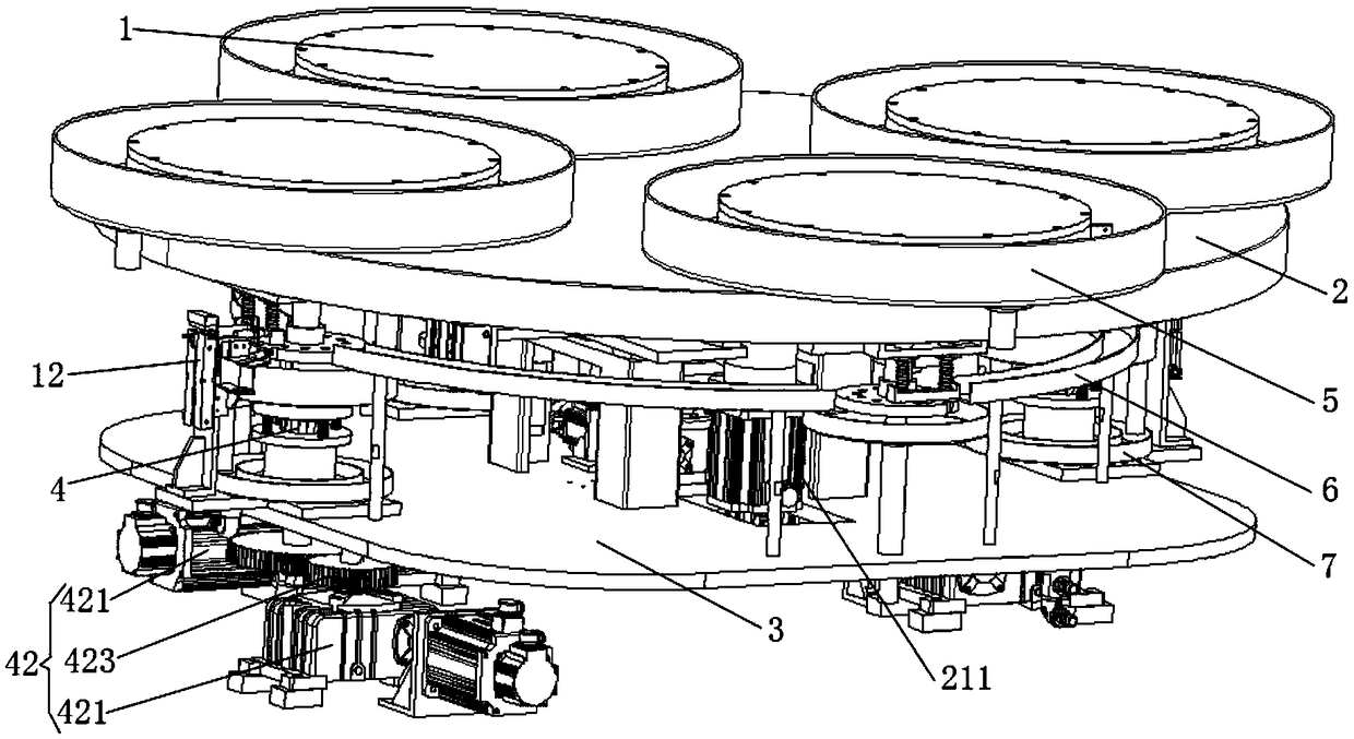
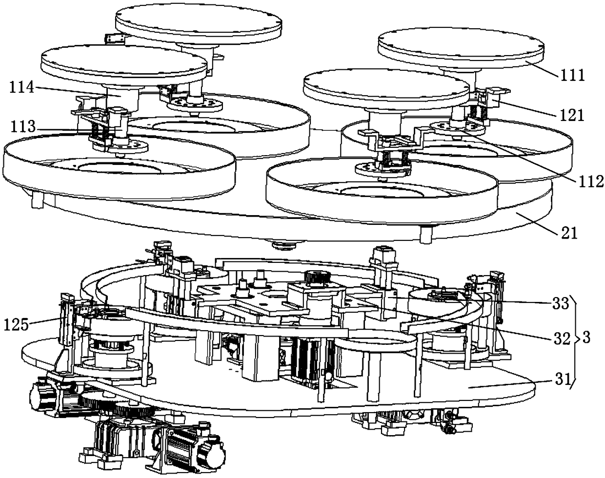
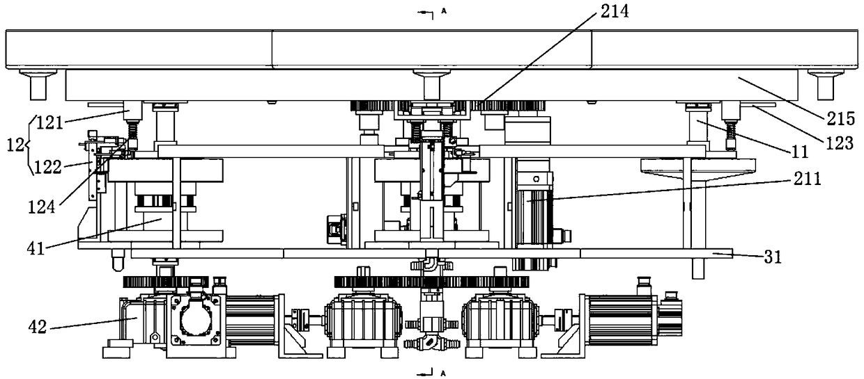
[0036] refer to Figure 1 to Figure 4 As shown, the present invention provides a lower working disc device of an intelligent precision polishing machine. The present invention comprises: a plurality of operation units 1, a work disk rotation mechanism 2, a work disk lifting mechanism 3 and a plurality of operation deceleration mechanisms 4, the tops of the several operation units 1 are respectively arranged on the work disk rotation mechanism 2, the several The bottom of the working unit 1 passes through the work disk rotating mechanism 2 and connects with the operation deceleration mechanism 4, and the work disk rotation mechanism 2 and several operation deceleration mechanisms 4 are respectively arranged on the work disk lifting mechanism 3; The working disc lifting mechanism 3 drives the working unit 1 above the working disc rotating mech...


PUM


Abstract

The invention discloses a lower working tray device of an intelligent precision polishing machine. The lower working tray device of the intelligent precision polishing machine comprises a working unit, a working tray rotating mechanism, a working tray lifting mechanism, and a working retarding mechanism, wherein the working unit is arranged on the working tray rotating mechanism; the working unitpenetrates out of the working tray rotating mechanism and then is connected with the working retarding mechanism; the working tray rotating mechanism and the working retarding mechanism are arranged on the working tray lifting mechanism; the working tray lifting mechanism drives the working unit to rise and fall, so that the connection or the separation of the working unit and the working retarding mechanism are controlled; the working retarding mechanism drives the working unit to rotate around the axis thereof; and the working tray rotating mechanism drives the working unit to switch workingposition. By using of the lower working tray device of the intelligent precision polishing machine, the working position switching is achieved; the working tray polishing operations do not interferewith each other and are carried out independently, one or more work pieces can be processed at the same time according to requirements, and the versatility is high; and the stop control and positioning of the targeted working tray without affecting the processing of other working trays are achieved, so that the machining efficiency is improved.

Description

technical field [0001] The invention relates to the technical field of polishing machines, in particular to a lower working disc device of an intelligent precision polishing machine. Background technique [0002] Polishing refers to the use of mechanical, chemical or electrical methods to reduce the surface roughness of the workpiece to obtain a bright and smooth surface. It is a processing method that uses polishing tools and abrasive particles or other polishing media to modify the surface of the workpiece. When the workpiece to be polished is placed on the working disc for polishing, in order to ensure that the curved surface of the workpiece is polished evenly, the working disc is generally set as a rotating working disc. [0003] There are following disadvantages in existing polishing machines: [0004] 1. The existing polishing machine cannot realize the switching of the working position of the working disc, the polishing operation of the working disc cannot be carrie...

Claims


Application Information

Patent Timeline
IPC IPC(8): B24B29/02B24B41/06B24B55/03
CPCB24B29/02B24B41/06B24B55/03
Inventor 高令谭志强李叶明黄忠胜曾祥禄
Owner SHENZHEN XIKEO IND CO LTD
Why Eureka
Try Eureka