Fault detection method and device

A fault detection and identification technology, applied in manufacturing auxiliary devices, processing data acquisition/processing, additive processing, etc., can solve the problems of printing failure, long time consumption, low efficiency, etc., and achieve the effect of improving work efficiency

Active Publication Date: 2019-03-01
BEIHANG UNIV
View PDF5 Cites 20 Cited by
  • Summary
  • Abstract
  • Description
  • Claims
  • Application Information

AI Technical Summary

Problems solved by technology

[0003] However, in the prior art, it takes a long time to print a complete usable product, and it is easy to cause printing failure problems due to lack of materials or 3D printing machine failures during the printing process. The supervision of the printing status of 3D printers is mainly through manpower, which is inefficient

Method used


Image

  • Fault detection method and device
  • Fault detection method and device
  • Fault detection method and device

Examples


Embodiment 1

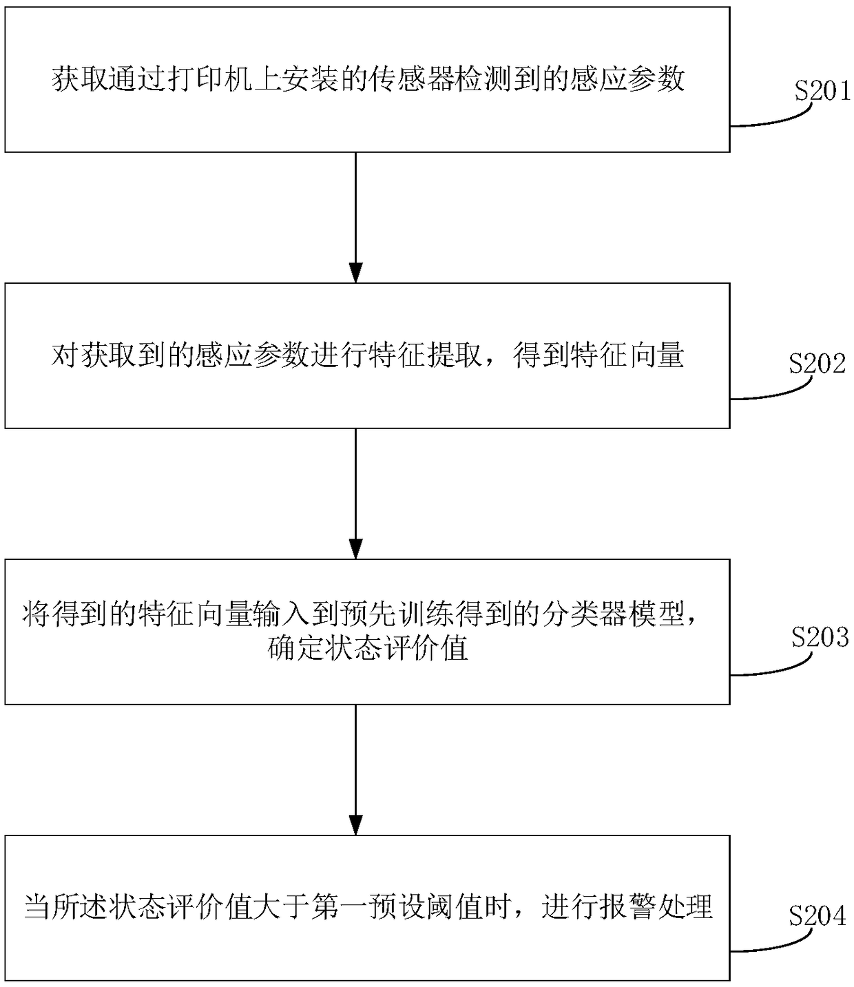
[0069] see figure 2 As shown, it is a schematic flowchart of a fault detection method and device provided in the embodiment of the present application, including the following steps:

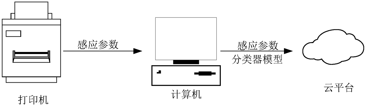
[0070] S201. Obtain a sensing parameter detected by a sensor installed on the printer.

[0071] In a possible implementation manner, the printer may be a 3D printer; the sensor may be a vibration sensor and an acceleration sensor; the sensing parameter may be a frequency detected by the vibration sensor and an acceleration detected by the acceleration sensor.

[0072] Before obtaining the sensing parameters through the sensor, the sensor can be debugged first, for example, the sensitivity of the sensor can be debugged.

[0073] In the embodiment of the present application, a vibration sensor and an acceleration sensor are used, but in practical applications, it is not limited to these two sensors. For example, other optional sensors, such as temperature and humidity sensors, may also be used....

Embodiment 2

[0126] The embodiment of the present application provides a fault detection device, referring to Figure 7 As shown, it is a schematic diagram of the structure of the fault monitoring device 700 provided by the embodiment of the present application. The device 700 includes: an acquisition module 701 , a feature extraction module 702 , a determination module 703 and an alarm module 704 .

[0127] Specifically, the obtaining module 701 is configured to obtain sensing parameters detected by sensors installed on the printer, wherein the sensing parameters are used to reflect the current working state of the printer;

[0128] A feature extraction module 702, configured to perform feature extraction on the acquired sensing parameters to obtain a feature vector;

[0129] A determining module 703, configured to input the obtained feature vectors into a pre-trained classifier model to determine a state evaluation value, wherein the state evaluation value is used to reflect the possibil...

Embodiment 3

[0149] like Figure 8 As shown, a schematic structural diagram of an electronic device 800 provided in Embodiment 4 of the present application includes: a processor 801, a memory 802, and a bus 803;

[0150] The above-mentioned memory 802 stores machine-readable instructions executable by the above-mentioned processor 801 (for example, including Figure 7 The acquisition module 701, the feature extraction module 702, the determination module 703, and the execution instructions corresponding to the alarm module 704, etc.), when the electronic device 800 is running, the above-mentioned processor 801 and the above-mentioned memory 802 communicate through the bus 803, and the above-mentioned machine can When the read instruction is executed by the above-mentioned processor 801, the following processing is performed:

[0151] acquiring sensing parameters detected by sensors installed on the printer, wherein the sensing parameters are used to reflect the current working state of th...


PUM


Abstract

The invention provides a fault detection method and device, wherein the method comprises the following steps of obtaining sensing parameters detected by a sensor arranged on a printer, wherein the sensing parameters are used for reflecting the current work state of the printer; then, performing feature extraction on the obtained sensing parameters to obtain feature vectors; next, inputting the obtained feature vectors into a classifier model obtained through pretraining, and determining the state evaluation value, wherein the state evaluation value is used for reflecting occurring possibilityof a printer fault; and finally, performing warning treatment when the state evaluation value is greater than the first preset threshold value. By using the mode, the work state of the printer can bemonitored in real time, and the warning is performed in case of the printer fault, so that the work efficiency is improved.

Description

technical field [0001] The present application relates to the technical field of fault detection, in particular to a fault detection method and device. Background technique [0002] As a kind of rapid prototyping technology, three-dimensional (3Dimensions, 3D) printing technology can quickly enter people's lives by virtue of its advantages of generating almost arbitrary complex parts without molds and tools, and greatly improves production efficiency. . [0003] However, in the prior art, it takes a long time to print a complete usable product, and it is easy to cause printing failure problems due to lack of materials or 3D printing machine failures during the printing process. The supervision of the printing status of 3D printers is mainly through manpower, which is inefficient. SUMMARY OF THE INVENTION [0004] In view of this, the purpose of this application is to provide a fault detection method and device to monitor the status of the 3D printer in real time and give...

Claims


Application Information

Patent Timeline
Patent Type & Authority Applications(China)
IPC IPC(8): B29C64/386B29C64/393B33Y50/00B33Y50/02
CPCB29C64/386B29C64/393B33Y50/00B33Y50/02
Inventor 张霖李冰赖李媛君罗啸任磊
Owner BEIHANG UNIV
Why Eureka
Try Eureka