Coreless rolling tool

A tooling and winding roller technology, which is applied in the field of coreless winding tooling, can solve the problems of deviation of the substrate, unwinding, and space occupied by the winding core, so as to improve the tightness, reduce the workload, and ensure the winding. tightness effect

Inactive Publication Date: 2019-03-01
FOSHAN GOLD SILVER RIVER INTELLIGENT EQUIP CO LTD
View PDF8 Cites 3 Cited by
  • Summary
  • Abstract
  • Description
  • Claims
  • Application Information

AI Technical Summary

Problems solved by technology

Among them, the surface winding is realized by using the friction between the roller and the substrate, but it is easy to cause the winding to be loose, causing the substrate to deviate, etc.; while the center winding needs to be realized by the air shaft, so that The operation of the staff is relatively hard, and the winding core will occupy a large part of the space, resulting in a shorter actual length of the coil and a reduction in the amount of winding

Method used


Image

  • Coreless rolling tool
  • Coreless rolling tool

Examples


Embodiment Construction

[0021] The core of this specific embodiment is to provide a coreless winding tool, which can ensure the tightening degree of the base material without affecting the winding volume, and solves the current problem in this field.

[0022] Hereinafter, an embodiment will be described with reference to the drawings. In addition, the examples shown below do not limit the content of the invention described in the claims in any way. In addition, all the contents of the configurations shown in the following embodiments are not limited to be essential to the solution of the invention described in the claims.

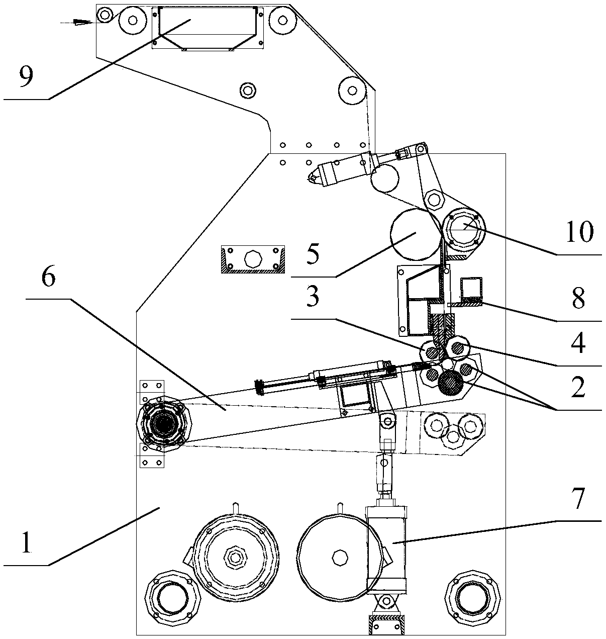
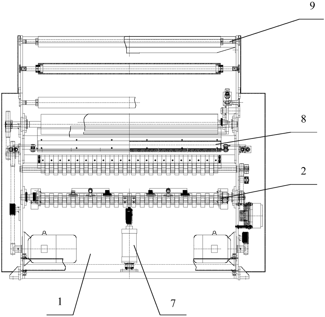
[0023] For the coreless winding tooling provided in this specific embodiment, please refer to Figure 1-2 comprising frame 1 and the upper winding roller and the lower winding roller 2 arranged on the frame 1, the upper winding roller is a plurality, and the upper winding roller and the lower winding roller 2 can form a space structure, which can The substrate to be rolled is co...


PUM


Abstract

The invention discloses a coreless rolling tool which comprises a rack as well as a plurality of upper rolling rollers and a lower rolling roller arranged on the rack, wherein the upper rolling rollers and the lower rolling roller define a space structure; and to-be-rolled base material can be compressed in the space structure. During the actual rolling process, the upper rolling rollers and the lower rolling roller take self as the axis to rotate simultaneously clockwise or anticlockwise, and through friction between the peripheral surface of each of the upper rolling rollers and the base material and friction between the peripheral surface of the lower rolling roller and the base material, coreless rolling of the base material is realized. The rolling process can realize coreless rollingof the base material, so that the rolling quantity of the base material is not affected; in addition, the upper rolling rollers and the lower rolling roller define the space structure for accommodating the base material, that is the upper rolling rollers and the lower rolling roller are distributed at different positions of the rolled base material, so that the tightening degree of the base material is increased; and moreover, an air shaft is not needed, so that the workload of an operator is reduced.

Description

technical field [0001] The invention relates to the field of printing, more specifically, to a coreless winding tool. Background technique [0002] In printing machinery, the commonly used winding methods are mainly divided into surface winding and center winding. Among them, the surface winding is realized by using the friction between the roller and the substrate, but it is easy to cause the winding to be loose, causing the substrate to deviate, etc.; while the center winding needs to be realized by the air shaft, so that The operation of the staff is relatively hard, and the winding core will occupy a large part of the space, resulting in a shorter actual length of the coil and a reduction in the amount of winding. [0003] Therefore, how to ensure the tightness of the base material without affecting the winding volume is an urgent problem to be solved in this field at this stage. Contents of the invention [0004] In view of this, the object of the present invention ...

Claims


Application Information

Patent Timeline
Patent Type & Authority Applications(China)
IPC IPC(8): B65H18/16
CPCB65H18/16B65H2701/1133
Inventor 杨超群
Owner FOSHAN GOLD SILVER RIVER INTELLIGENT EQUIP CO LTD
Why Eureka
Try Eureka