Wire guiding cam of high-speed winding machine

A winding machine and guide wire technology, which is applied in the direction of conveying filamentous materials, thin material processing, transportation and packaging, etc., can solve the problems of increased cost and long time consumption of grooved drums, and achieve improved stability and convenience sexual effect

Pending Publication Date: 2019-03-01
江苏汤氏纺机集团有限公司
View PDF0 Cites 2 Cited by
  • Summary
  • Abstract
  • Description
  • Claims
  • Application Information

AI Technical Summary

Problems solved by technology

[0002] The guide wire cam is one of the important winding parts on the grooved drum winder. The yarn tension and winding density are the main basis for measuring the quality of the bobbin during winding. The curve shape of the spiral groove on the upper distribution has a direct impact on the shape of the tube. Today's guide wire cam needs to unscrew the external bolts in sequence and replace it in the process of replacing the grooved tube. This replacement The process takes a long time. At the same time, the rotating shaft and the fixed sleeve are fixedly connected. When the tank fails, it needs to be replaced as a whole, which leads to an increase in the use cost of the tank.

Method used


Image

  • Wire guiding cam of high-speed winding machine
  • Wire guiding cam of high-speed winding machine
  • Wire guiding cam of high-speed winding machine

Examples


Embodiment Construction

[0024] The following will clearly and completely describe the technical solutions in the embodiments of the present invention with reference to the accompanying drawings in the embodiments of the present invention. Obviously, the described embodiments are only some, not all, embodiments of the present invention. Based on the embodiments of the present invention, all other embodiments obtained by persons of ordinary skill in the art without making creative efforts belong to the protection scope of the present invention.

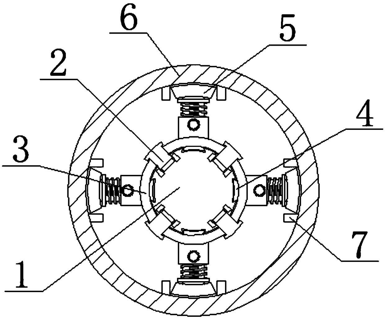
[0025] Such as figure 1 As shown, a guide wire cam of a high-speed winder includes a rotating rod 1, the top of the front side of the rotating rod 1 is fixedly equipped with a fixing mechanism 2, and the outer surface of the rotating rod 1 is movably sleeved with a fixed sleeve 3, fixed The top of the inner cavity of the sleeve 3 is fixedly installed with a block 4, and the top of the fixed sleeve 3 is fixedly installed with a limit mechanism 5, and the outer ...


PUM


Abstract

The invention relates to the technical field of wire guiding cams, and discloses a wire guiding cam of a high-speed winding machine. The wire guiding cam of the high-speed winding machine comprises arotary rod, wherein a fixed mechanism is arranged on the top part of one side of the front surface of the rotary rod; a fixed sleeve is arranged on the outer surface of the rotary rod; a fixture blockis arranged on the top part of an inner cavity of the fixed sleeve; a limiting mechanism is arranged on the top part of the fixed sleeve; a groove drum is arranged on the outer surface of the limiting mechanism; a limiting block is arranged on the top part of an inner cavity of the groove drum; and a groove is formed in the front surface of the groove drum. According to the wire guiding cam of the high-speed winding machine, through arranging the fixed mechanism, the rotary rod and the fixed sleeve are connected conveniently, so that the problem of instability in connection of the rotary rodand the fixed sleeve is solved, and the stability between the rotary rod and the fixed sleeve is improved; and through arranging the limiting mechanism, the groove drum can be conveniently replaced, so that the problem that much more time needs to be spent during the groove drum replacement process is solved, and the convenience in replacing the groove drum is improved.

Description

technical field [0001] The invention relates to the technical field of wire guide cams, in particular to a wire guide cam of a high-speed winding machine. Background technique [0002] The guide wire cam is one of the important winding parts on the grooved drum winder. The yarn tension and winding density are the main basis for measuring the quality of the bobbin during winding. The curve shape of the spiral groove on the upper distribution has a direct impact on the shape of the tube. Today's guide wire cam needs to unscrew the external bolts in sequence and replace it in the process of replacing the grooved tube. This replacement The process takes a long time, and at the same time, the rotating shaft and the fixed sleeve are fixedly connected. When the tank drum fails, it needs to be replaced as a whole, which leads to the problem of increased use cost of the tank drum. Contents of the invention [0003] (1) Solved technical problems [0004] Aiming at the deficiencies...

Claims


Application Information

Patent Timeline
Patent Type & Authority Applications(China)
IPC IPC(8): B65H54/48
CPCB65H54/48B65H2701/31
Inventor 汤坚
Owner 江苏汤氏纺机集团有限公司
Why Eureka
Try Eureka