Top-rigid-and-bottom-flexible deep foundation pit supporting system and construction method thereof

A deep foundation pit support and system technology, applied in the direction of foundation structure engineering, excavation, sheet pile wall, etc., can solve the problems of inconvenient fully rigid support structure, slow construction progress, material waste cost, etc., to reduce the difficulty of earthwork excavation , saving construction period and low cost

Pending Publication Date: 2019-03-01
CHINA CONSTR FIRST DIV GROUP CONSTR & DEV
View PDF0 Cites 1 Cited by
  • Summary
  • Abstract
  • Description
  • Claims
  • Application Information

AI Technical Summary

Problems solved by technology

[0003] The purpose of the present invention is to provide a deep foundation pit support system with a rigid top and a flexible bottom and its construction method. It is necessary to solve the problem of the underground structure and underground pipelines of the surrounding existing buildings (structures) so that there is no flexible anchor member within a certain depth. The technical problems of the construction conditions and the technical problems of the use of a fully rigid support structure are not convenient for earthwork excavation, the construction progress is slow, material waste and high cost

Method used


Image

  • Top-rigid-and-bottom-flexible deep foundation pit supporting system and construction method thereof
  • Top-rigid-and-bottom-flexible deep foundation pit supporting system and construction method thereof
  • Top-rigid-and-bottom-flexible deep foundation pit supporting system and construction method thereof

Examples


Embodiment Construction

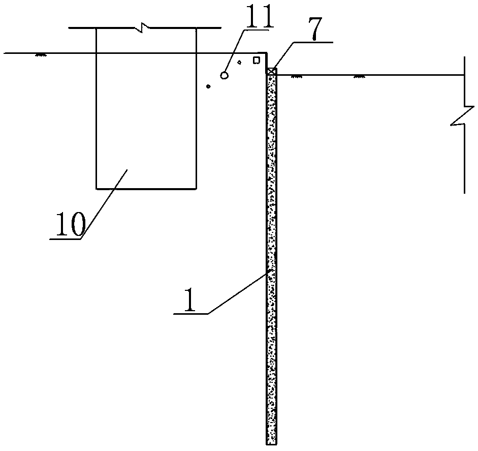
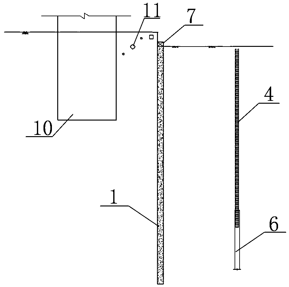
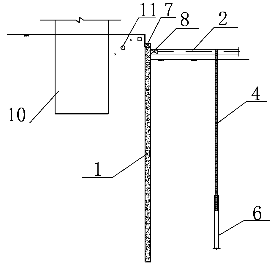
[0039] In this embodiment, the deep foundation pit support system with rigid upper and lower soft is used in the basement of the existing building 10 beside the foundation pit, and various pipelines 11 are buried in the foundation, subway tunnel, entrance and exit, and underground.

[0040] like Figure 1-7 As shown in the figure, this deep foundation pit support system with rigid upper and lower softness includes vertical support members 1 arranged along the edge of the foundation pit 5, rigid support members 2 supported on the upper part of the vertical support member 1, and pull The flexible anchor member 3 is arranged at the lower part of the vertical support member 1; the rigid support member 2 has at least two rows, which are arranged at intervals in the vertical direction; wherein, the rigid support members 2 of each row are arranged vertically and horizontally in the same horizontal plane; The flexible anchor members 3 have at least two rows, which are arranged in a pl...


PUM

PropertyMeasurementUnit
Lengthaaaaaaaaaa

Abstract

The invention relates to a top-rigid-and-bottom-flexible deep foundation pit supporting system and a construction method thereof. The top-rigid-and-bottom-flexible deep foundation pit supporting system comprises vertical shoring members, rigid supporting members and flexible pulling anchor members; at least two rows of rigid supporting members are arranged in the vertical direction at interval; each row of rigid supporting members are arranged vertically and horizontally in the same horizontal plane in a crossed manner; the at least two rows of flexible pulling anchor members are arranged; thedistance between the flexible pulling anchor members on the bottommost row and the bottom of a foundation pit is not less than 2 m, and the distance between the flexible pulling anchor members on thetopmost row and the rigid supporting members on the bottommost row is 2 m to 4 m; and one ends of the flexible pulling anchor members are connected to the vertical shoring members, and the other endsof the flexible pulling anchor members are anchored into soil bodies at the backs of the flexible pulling anchor members. The top-rigid-and-bottom-flexible deep foundation pit supporting system and the construction method solve the technical problem about the construction condition that an underground structure and an underground pipeline of an existing building (structure) on the periphery avoidthe flexible pulling anchor members within a certain depth, and solve the technical problems that when a full rigid supporting structure is adopted, earth excavation is inconvenient, the constructionprogress is slow, materials are wasted, and the cost is high.

Description

technical field [0001] The invention relates to the field of construction engineering, in particular to a deep foundation pit support system with rigid upper and lower soft and a construction method thereof. Background technique [0002] With the acceleration of urbanization in my country, the development and utilization of urban underground space has become a worldwide development trend, and the foundation pit project is constantly developing in the direction of extra-large and super-deep. For deep foundation pits with complex geological conditions, high requirements for deformation control, or existing underground structures (structures), underground pipelines, and construction conditions without flexible anchor members within a certain depth, in order to ensure the safety of foundation pits, deep foundation pits are The pit support form usually chooses earth retaining (water) members + rigid anchor members, but the use of multiple rigid anchor members such as internal sup...

Claims


Application Information

Patent Timeline
IPC IPC(8): E02D17/04E02D5/76
CPCE02D5/76E02D17/04
Inventor 周予启刘卫未聂艳侠马书杰刘广济郭恒
Owner CHINA CONSTR FIRST DIV GROUP CONSTR & DEV
Why Eureka
Try Eureka