Novel prefabricated frame structure

A frame structure, a new type of technology, applied in the direction of building components, building structures, building materials, etc., can solve the problems of heavy construction work, limited prefabricated parts, shortened construction period, etc., to reduce construction waste, reduce noise and Dust pollution and the effect of shortening the construction period

Pending Publication Date: 2019-03-01
YAU LEE WAH CONSTRUCTION MATERIALS (HUIZHOU) COMPANY LIMITED
View PDF0 Cites 3 Cited by
  • Summary
  • Abstract
  • Description
  • Claims
  • Application Information

AI Technical Summary

Problems solved by technology

[0003] However, the prefabricated parts used in the existing building structures are limited, and a large number of structures still need to use cast-in-place concrete, so the on-site construction workload is still very large, and the construction period cannot be further shortened

Method used


Image

  • Novel prefabricated frame structure
  • Novel prefabricated frame structure
  • Novel prefabricated frame structure

Examples


Embodiment 1

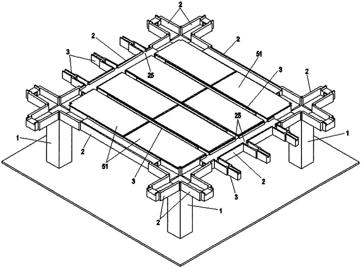
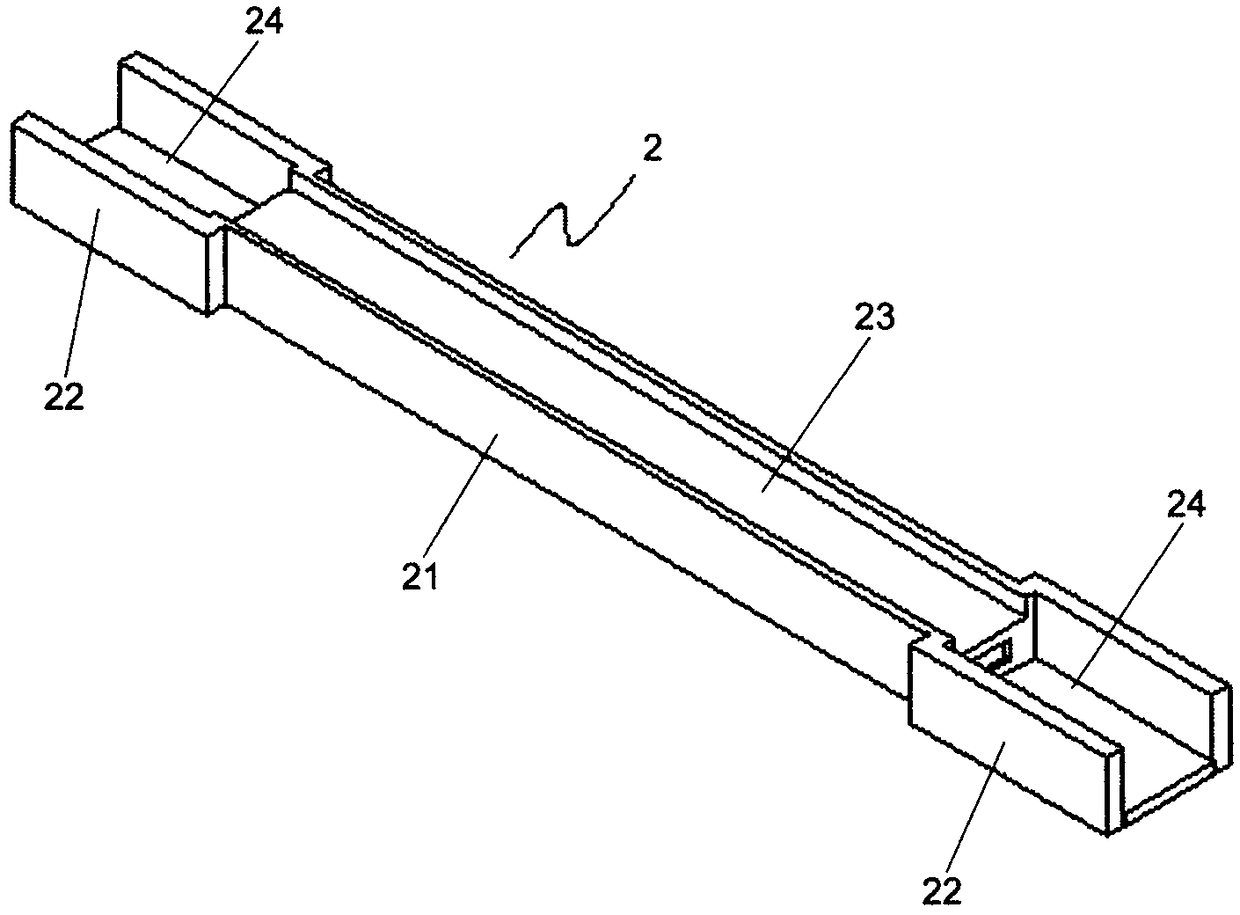
[0039] Embodiment one, as figure 2 As shown, the width of the two ends 22 of the main girder 2 is larger than the width of the middle part 21, and the middle part 21 and the end part 22 are connected in a stepped shape. The tops of the middle part 21 of the main beam 2 and the tops of both ends 22 are respectively provided with recesses 23 and 24, wherein the recess 23 of the middle part 21 is relatively shallow, and the recess 24 of the end part 22 is deep and penetrates to the end surface of the main beam 2. 21 both sides and end 22 both sides are of the same height. When pouring concrete on the floor, the recesses 23 and 24 at the top of the main beam 2 are also cast-in-place concrete to form the cast-in-place part of the main beam 2 .

Embodiment 2

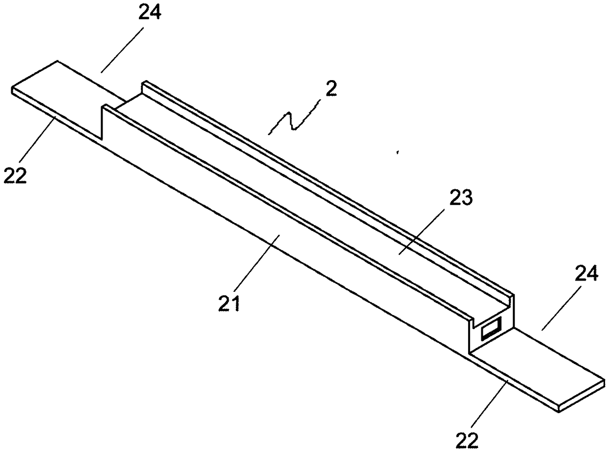
[0040] Embodiment two, such as image 3 As shown, different from the first embodiment of the main beam, the width of the two ends 22 of the main beam 2 is equal to the width of the middle part 21, and the height of both sides of the end 22 is much lower than the height of both sides of the middle part 21, so the end A small amount of formwork is required on both sides of 22 for sealing.

[0041] Similarly, in the present invention, the secondary beam 3 can also adopt the following two structural modes:

[0042] Embodiment one, as Figure 4 As shown, the widths of the two ends 32 of the secondary beam 3 are larger than the width of the middle part 31 , and the middle part 31 and the end parts 32 are connected in steps. The tops of the middle part 31 of the secondary beam 3 and the tops of both ends 32 are respectively provided with recesses 33 and 34, wherein the recess 33 of the middle part 31 is relatively shallow, and the recess 34 of the end part 32 is relatively deep and...


PUM


Abstract

The invention discloses a novel prefabricated frame structure. The novel prefabricated frame structure comprises vertical columns (1), main beams (2), secondary beams (3) and a floor (5); the main beams (2) and the secondary beams (3) adopt prefabricated members and are provided with reserved and exposed steel bars; the floor (5) is a laminated board, a prefabricated board (51) is adopted on the bottom of the floor, and concrete is cast in situ on the top parts of the prefabricated board (51), the main beams (2) and the secondary beams (3) to combine the prefabricated board (51), the main beams (2) and the secondary beams (3); reserved and exposed steel bars are arranged at the tops of the vertical columns (1), prefabricated columns of to-be-cast structures are arranged at the bottoms of the vertical columns, the to-be-cast structures are used for being connected to a lower layer building structure, exposed steel bars of the lower layer building structure is inserted inside the to-be-cast structures, and the connection between the vertical columns (1) and the lower layer building structure is realized by in-situ casting of concrete in the to-be-cast structures. According to the novel prefabricated frame structure, on-site construction working quantity can be effectively lowered, pollution and wasting are decreased, human resources are greatly lowered, construction efficiency iseffectively improved, and the construction period is shortened.

Description

technical field [0001] The invention relates to a building structure, in particular to a novel prefabricated frame structure, which is especially suitable for all frame structures or frame-shear structures. Background technique [0002] The main prefabricated parts used in traditional frame structure buildings constructed by prefabricated parts assembly mode are: prefabricated secondary beams and prefabricated slabs. During construction, the column should be cast in place first, then the prefabricated secondary beam, prefabricated slab and cast-in-place main beam reinforcement should be installed, and finally the concrete should be cast in-situ on the prefabricated slab to combine the main beam, prefabricated secondary beam and prefabricated slab. The use of prefabricated parts can reduce the amount of on-site construction work, save labor and improve construction efficiency. [0003] However, the prefabricated parts used in the existing building structures are limited, and...

Claims


Application Information

Patent Timeline
Patent Type & Authority Applications(China)
IPC IPC(8): E04B1/19
CPCE04B1/19E04B2001/1924E04B2001/1975E04B5/38E04B5/43E04B1/20E04B1/2403E04B1/30E04B2/7425E04B2001/1918E04C1/24E04C3/34E04G21/14
Inventor 黄天祥黄慧敏
Owner YAU LEE WAH CONSTRUCTION MATERIALS (HUIZHOU) COMPANY LIMITED
Why Eureka
Try Eureka