
Special-shaped steel column concrete filling construction method and concrete

A construction method and concrete technology, applied in the direction of columns, pier columns, pillars, etc., can solve the problems of difficult pouring and high pouring cost, and achieve the effect of reducing construction cost, reducing construction time and improving quality

Inactive Publication Date: 2019-03-01
上海宝钢工程咨询有限公司
View PDF3 Cites 2 Cited by
  • Summary
  • Abstract
  • Description
  • Claims
  • Application Information

AI Technical Summary

Problems solved by technology

[0005] The purpose of the present invention is to provide a special-shaped steel column concrete pouring construction method to solve the existing technical problems of special-shaped steel column concrete pouring difficulty and high pouring cost

Method used


Image

  • Special-shaped steel column concrete filling construction method and concrete
  • Special-shaped steel column concrete filling construction method and concrete
  • Special-shaped steel column concrete filling construction method and concrete

Examples


Embodiment 1

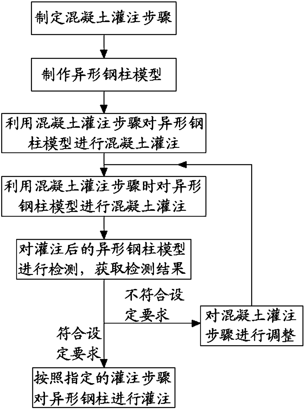
[0042] This embodiment discloses a special-shaped steel column concrete pouring construction method, such as image 3 shown, image 3 This is the flow chart of the construction method provided in this embodiment. The described construction method includes the following steps:

[0043] S1: formulate concrete pouring steps;

[0044] S2: Make a special-shaped steel column model;

[0045] For S2, since the skew-grid steel structure contains a plurality of the special-shaped steel columns, it is not practical to manufacture the entire skew-grid steel structure for simulation tests. Therefore, one or more of many special-shaped steel columns can be selected as a reference to make the special-shaped steel column model. Of course, several representative ones can also be selected according to the shape of the special-shaped steel column. For example, the special-shaped steel column includes a K-shaped steel column and an X-shaped steel column, so one K-shaped steel column can be pr...

Embodiment 2

[0062] Due to the high difficulty of pouring the special-shaped steel column described in Example 1, the existing self-compacting concrete is difficult to meet the pouring requirements for the special-shaped steel column. Therefore, this embodiment also provides a concrete for pouring the special-shaped steel column, the concrete can flow better in the inner space of the special-shaped steel column, so as to avoid the occurrence of failure due to inability to vibrate or insufficient vibration. Defects such as voids, honeycombs and pockmarks are produced. The concrete includes the following components:

[0063]

[0064] The flow performance of the concrete prepared by the above content is increased, and the defect of poor flowability of the existing concrete is overcome, so that it can be applied to the special-shaped steel column in Example 1, and can also be used for difficult or even impossible to pour. In the structural part, defects such as voids, honeycombs and pockma...


PUM


Abstract

The invention relates to the technical field of building construction, particularly to a special-shaped steel column concrete filling construction method and concrete. The special-shaped steel columnconcrete filling construction method comprises the following steps of designing concrete filling processes; manufacturing a special-shaped steel column model; filling concrete into the special-shapedsteel column model according to the concrete filling processes; detecting the concrete-filled special-shaped steel column model to obtain a detecting result; analyzing the detecting result, and if thedetecting result meets design requirements, concrete-filling a special-shaped steel column according to the concrete filling process; otherwise, adjusting the concrete filling processes until the detecting result meets the design requirements. By performing simulation tests during filling construction and gradually correcting and improving the filling processes, the special-shaped steel column concrete filling construction method can greatly improve the special-shaped steel column concrete filling quality and reduce the construction cost.

Description

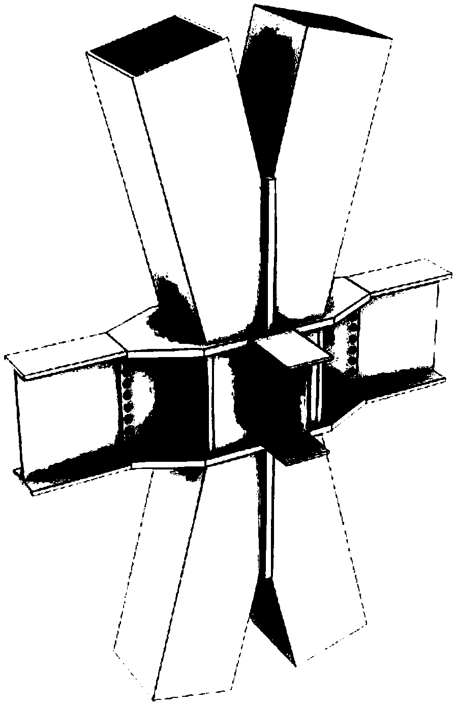
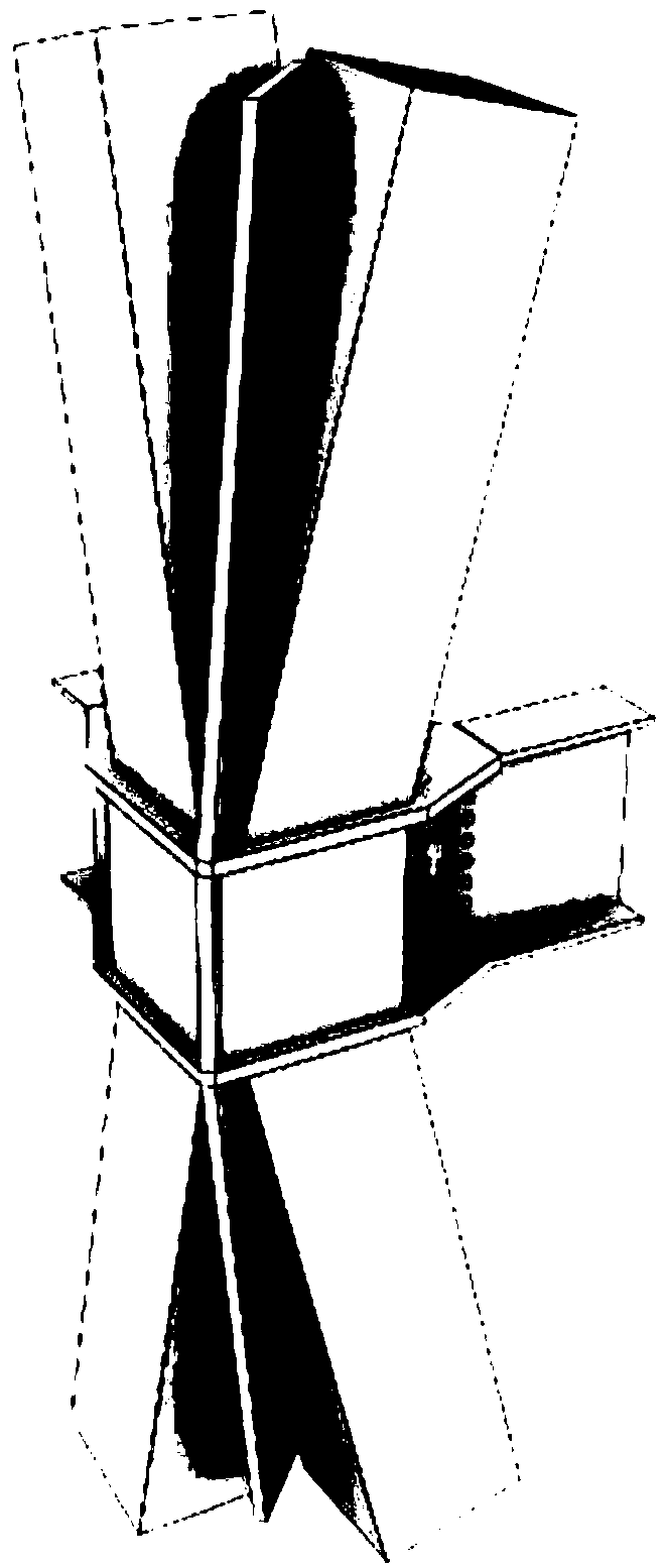
technical field [0001] The invention relates to the technical field of building construction, in particular to a special-shaped steel column concrete pouring construction method and concrete. Background technique [0002] At present, in construction, many tower projects use large-scale diagonal grid steel structure as the main support. These large-scale diagonal grid steel structures are composed of straight and slanted steel columns. After the grid steel structure is formed, it is also necessary to perform concrete pouring on the straight steel columns and inclined steel columns in the diagonal grid steel structure to achieve various performance indicators. [0003] Due to the diverse shapes and large numbers of inclined steel columns, they are collectively referred to as special-shaped steel columns. In actual concrete pouring construction, special-shaped steel columns usually include X-shaped steel columns and K-shaped steel columns, such as figure 1 and 2 shown. Sin...

Claims


Application Information

Patent Timeline
IPC IPC(8): E04C3/34E04B1/30E04B1/58C04B28/02C04B111/70
CPCC04B28/02C04B2111/70E04B1/185E04B1/30E04C3/34C04B18/12C04B14/06C04B14/02C04B2103/302
Inventor 李岗
Owner 上海宝钢工程咨询有限公司
Learn More