
Well cementation tubular column and well cementation method

A cementing and tubing string technology, applied in wellbore/well components, earthwork drilling, sealing/isolation, etc., can solve problems such as difficult to estimate accurately, difficult to accurately grasp the volume of drilling fluid, etc., to improve the success rate and the effect of effectiveness

Active Publication Date: 2019-03-01
CHINA PETROLEUM & CHEM CORP +1
View PDF7 Cites 2 Cited by
  • Summary
  • Abstract
  • Description
  • Claims
  • Application Information

AI Technical Summary

Problems solved by technology

According to the current technology and situation, it is difficult to accurately grasp the volume of the drilling fluid that has been injected. In this case, it is even more difficult to estimate the downhole position where the cement slurry reaches

Method used


Image

  • Well cementation tubular column and well cementation method
  • Well cementation tubular column and well cementation method

Examples


Embodiment Construction

[0022] The present invention will be further described below in conjunction with accompanying drawing.

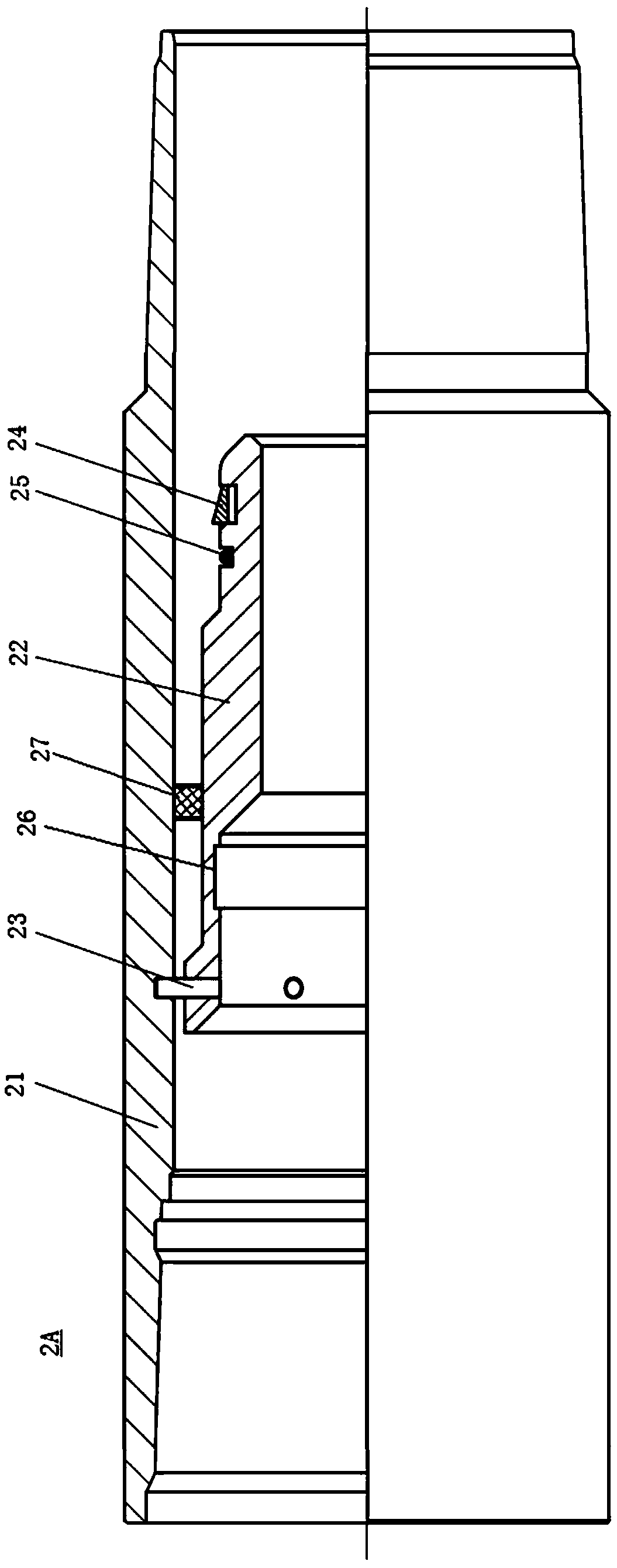
[0023] Such as figure 1 As shown, the cementing string 1 includes a bumper seat 3 and a positioning mechanism located upstream of the bumper seat 3 . The cementing string 1 may only include one positioning mechanism, or may include multiple positioning mechanisms, for example, may include two positioning mechanisms 2A, 2B (see figure 1 ). The positioning mechanism itself is set at a certain position of the cementing string 1, for example, the distance between the positioning mechanism and the wellhead is predetermined, that is, the downhole depth where the positioning mechanism is located is certain. In this case, when the cementing plug used to separate the cement slurry and the replacement fluid reaches the determined position of the positioning mechanism, the positioning mechanism sends a positioning signal in response to the arrival of the cementing plug. figure 1 Th...


PUM


Abstract

The invention relates to a well cementation tubular column and a well cementation method. The well cementation tubular column includes a bumping pressure seat and at least one positioning mechanism which is arranged in the determined position on the upstream of the bumping pressure seat; and when a well cementation rubber plug arrives at the determined position, the positioning mechanisms respondto the arriving of the well cementation rubber plug so that a positioning signal can be sent. The downhole positions that cement mortar arrives can be more accurately determined through the well cementation tubular column.

Description

technical field [0001] The invention relates to the technical field of well cementing in the petroleum industry, in particular to a cementing pipe string. The present invention also relates to a well cementing method using the above cementing string. Background technique [0002] During the cementing process, drilling fluid is often used to replace the cement slurry, so as to send the cement slurry to the desired position downhole. If the downhole position where the cement slurry arrives deviates from the expected one, it will affect the cementing quality and have a great impact on the subsequent construction. [0003] In the prior art, the position of the cement slurry downhole is usually determined by methods such as tank metering or flowmeter metering. However, none of these methods can directly know the position of the cement slurry. For example, measurement by tank gauging involves estimating the downhole location where the cement slurry has reached by determining th...

Claims


Application Information

Patent Timeline
IPC IPC(8): E21B33/13
CPCE21B33/13
Inventor 赵晨熙程光明孔博陈秀华尹垒邓继文敖竹青曹海涛马善坤张辉
Owner CHINA PETROLEUM & CHEM CORP
Learn More